End mill

An end mill and cutting part technology, applied in milling cutters, milling machine equipment, manufacturing tools, etc., can solve the problems of increasing the difficulty of mold machining, reducing production efficiency, increasing labor input, etc., to ensure machining accuracy and service life, The effect of increasing the core thickness ratio and reducing the amount of cutting vibration

Inactive Publication Date: 2019-11-29
SUZHOU AHNO PRECISION CUTTING TECH CO LTD
View PDF0 Cites 1 Cited by
  • Summary
  • Abstract
  • Description
  • Claims
  • Application Information

AI Technical Summary

Problems solved by technology

However, during the mechanical forming process of the mould, there is the following problem: graphite and metal have opposite properties when heated, which manifests itself in the fact that the higher the temperature, the harder the structure
Moreover, graphite has good strength and low thermal expansion coefficient at high temperature, which virtually increases the difficulty of mold machining, resulting in fast wear and low life of milling tools such as conventional cemented carbide.
In addition, at present, cemented carbide or diamond-coated milling cutters are mainly used to perform the finishing process. Generally, the surface roughness after forming can only reach Ra0.4, which is far from meeting the requirements for use. Manual polishing will be added in the future, which will greatly increase Reduced manpower input and reduced production efficiency

Method used


Image

  • End mill
  • End mill
  • End mill

Examples


Embodiment Construction

[0030] In the description of the present invention, it should be understood that the orientation or positional relationship indicated by the terms "left", "right", etc. is based on the orientation or positional relationship shown in the drawings, and is only for the convenience of describing the present invention and simplifying the description. It is not intended to indicate or imply that the referred device or element must have a particular orientation, be constructed in a particular orientation, and operate in a particular orientation, and thus should not be construed as limiting the invention.

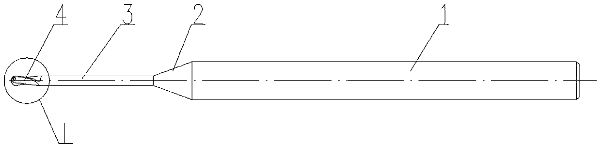
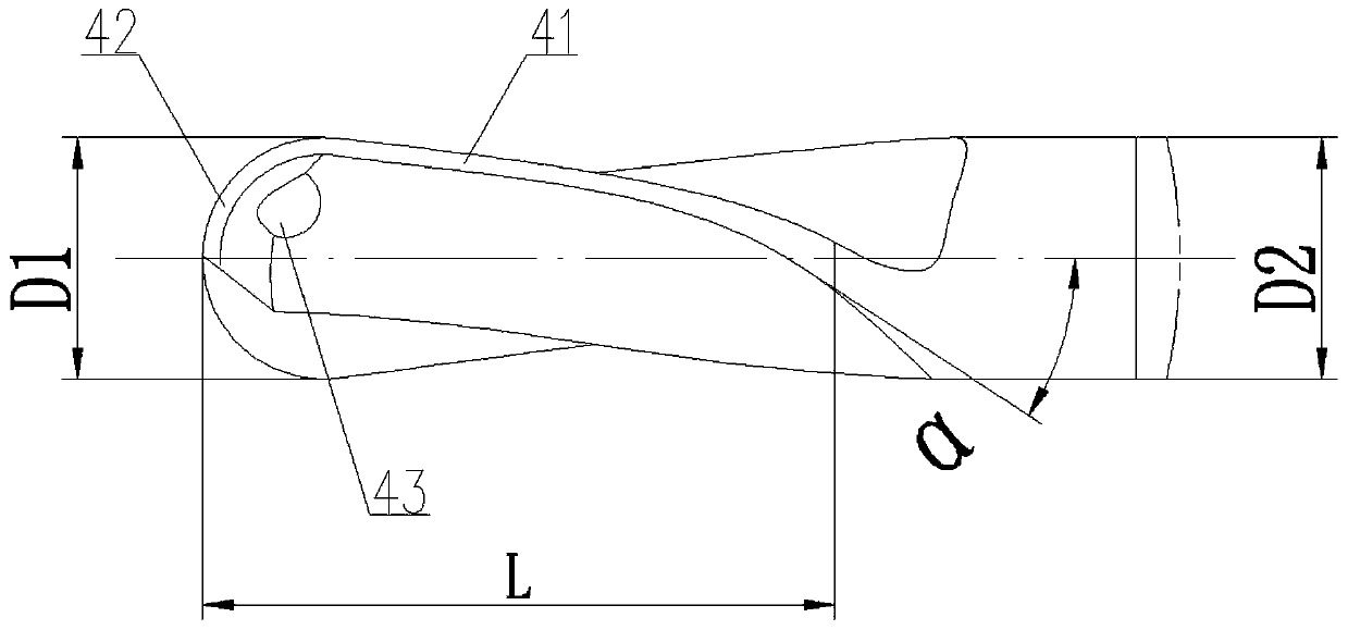
[0031] Below in conjunction with specific embodiment, content of the present invention is described in further detail, figure 1 It shows a schematic structural view of the first embodiment of the end mill in the present invention, which includes a shank 1, a tapered transition portion 2, a neck 3 and a cutting portion 4, which are sequentially connected as a whole along the directio...


PUM


Abstract

The invention relates to an end mill which is made of zirconia ceramics. The end mill comprises a handle part, a conical transition part, a neck part and a cutting part which are connected in sequence. The cutting part comprises at least two outer circle blades which spirally extend around the outer side wall of the cutting part, and the spiral angle alpha is controlled to be 25 degrees to 42 degrees. The circumference blade front angle beta of the outer circle blades is controlled to be 5 degrees to 10 degrees, and the circumference blade rear angle gamma of the outer circle blades is controlled to be 12 degrees to 18 degrees. The outer circle blades extend to the end face of the cutting part to form end blades, and the rear angle delta of the end blades is controlled to be 10 degrees to18 degrees. In addition, the outer diameter of the cutting part is D1, the core thickness diameter of the cutting part is d, and d is equal to 65%-70% of D1. Thus, in the practical cutting process, the end mill has the low cutting vibration amount, a cutting edge is not likely to be subjected to an oxidation chemical reaction, and therefore the machining precision and the service life are effectively ensured. In addition, the tripping phenomenon extremely happens in the specific use process of the end mill, and therefore the fine degree of the cutting edge is ensured.

Description

technical field [0001] The invention relates to the technical field of cutting tool manufacturing, in particular to an end mill. Background technique [0002] Nowadays, graphite is widely used in the mold manufacturing industry due to its good physical and chemical properties. For example, in the prior art, graphite is used as the material for manufacturing 3D glass hot bending molds. High, good electrical conductivity, radiation resistance, corrosion resistance, good thermal conductivity, low cost, high temperature resistance and other characteristics. However, there is a problem with mechanically forming molds: graphite and metal have opposite properties when heated, which means that the higher the temperature, the harder the structure. Moreover, graphite has good strength and low thermal expansion coefficient at high temperatures, which virtually increases the difficulty of mold machining, resulting in fast wear and low life of milling tools such as conventional cemented...

Claims


Application Information

Patent Timeline
Patent Type & Authority Applications(China)
IPC IPC(8): B23C5/10B23C5/28
CPCB23C5/1018B23C5/28B23C2210/04B23C2210/0485
Inventor 王弢杨路陈刚刘健
Owner SUZHOU AHNO PRECISION CUTTING TECH CO LTD
Why Eureka
Try Eureka