A cutting tool with guiding structure

A cutting tool and guide structure technology, which is applied in the direction of manufacturing tools, drilling tool accessories, boring machine/drilling machine parts, etc., can solve the problem of reducing the friction force and friction heat between the guide strip and the hole wall, burns on the processed surface, and wrapping Solve problems such as guide strips, achieve stable and reliable positioning structure, improve surface processing quality, and avoid rigid contact

Active Publication Date: 2021-10-01
ZHUZHOU CEMENTED CARBIDE CUTTING TOOLS CO LTD
View PDF7 Cites 1 Cited by
  • Summary
  • Abstract
  • Description
  • Claims
  • Application Information

AI Technical Summary

Problems solved by technology

[0003] For example, the publication number is CN105636728A Chinese patent literature discloses a guide block structure for cutting tools, which reduces the contact area through the middle avoidance groove, and relies on the external gap to flow cutting fluid to form a supporting protective film, thereby reducing the contact between the guide bar and the cutting tool. The frictional force and frictional heat between the hole walls, but due to the generally low pressure of the cutting fluid flowing in from the outside of this structure, it is difficult to completely envelop the guide strip during the high-speed cutting process of the tool, so it will inevitably cause the guide strip Rigid contact with the machined hole wall, which generates a lot of frictional heat and may even burn the machined surface

Method used


Image

  • A cutting tool with guiding structure
  • A cutting tool with guiding structure
  • A cutting tool with guiding structure

Examples


Embodiment Construction

[0024] The present invention will be further described in detail below in conjunction with the accompanying drawings and specific embodiments.

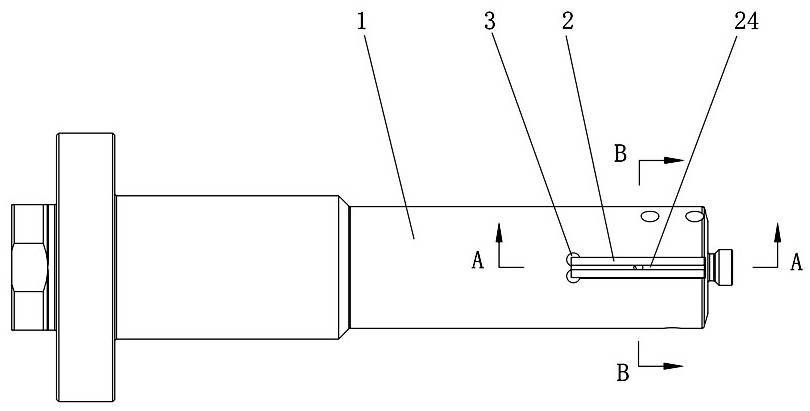
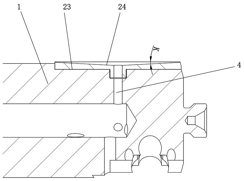
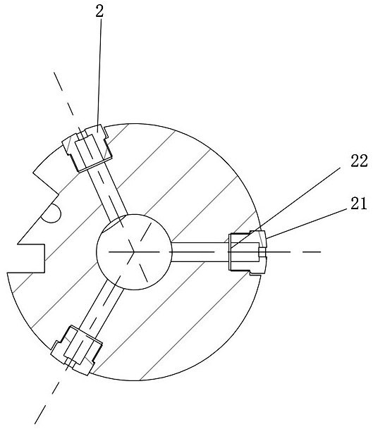
[0025] Figure 1 to Figure 6 Shown is an embodiment of the cutting tool with guiding structure of the present invention, the cutting tool with guiding structure includes cutting tool body 1, and also includes elongated guide bar 2, and the surface of cutting tool body 1 is provided with The guide cavity 3 that the guide bar 2 cooperates, the guide bar 2 includes a guide support surface 21, a bottom positioning surface 22 and a positioning column 23, the positioning column 23 is located on the bottom positioning surface 22, and a deep groove cavity 24 is provided on the guide support surface 21, The positioning column 23 is provided with a first cooling hole 25 communicating with the deep groove cavity 24. The guide cavity 3 includes a bottom supporting surface 31, a surrounding receiving surface 32 and a positioning hole 33. The posit...


PUM


Abstract

The invention discloses a cutting tool with a guide structure, which includes a cutting tool body and a long guide bar. A guide cavity matching the guide bar is provided on the surface of the cutting tool body. The guide bar includes a guide support surface, Bottom positioning surface and positioning column. The positioning column is located on the bottom positioning surface. A deep groove cavity is opened on the guiding support surface. The positioning column is provided with a first cooling hole communicating with the deep groove cavity. The guiding cavity includes a bottom supporting surface, a peripheral The receiving surface and the positioning hole, the positioning hole is opened on the bottom supporting surface, the bottom positioning surface is in contact with the bottom supporting surface, the surrounding receiving surface is located on both sides of the bottom supporting surface, the positioning column and the positioning hole are interference fit, and the cutting tool body is also provided with There is a second cooling hole connected to the first cooling hole, which has the advantages of small guiding contact area, small cutting vibration, stability and reliability.

Description

technical field [0001] The invention relates to the technical field of metal cutting, in particular to a cutting tool with a guiding structure. Background technique [0002] In the field of metal cutting, especially in the processing of large length-to-diameter ratio hole parts, the tool has a large cutting vibration, which affects the processing quality and tool life. Reducing the length-to-diameter ratio is the most effective way to suppress vibration, that is, setting the guide Common means in the prior art for support structures. [0003] For example, the publication number is CN105636728A Chinese patent literature discloses a guide block structure for cutting tools, which reduces the contact area through the middle avoidance groove, and relies on the external gap to flow into the cutting fluid to form a supporting protective film, thereby reducing the contact between the guide bar and the cutting tool. The frictional force and frictional heat between the hole walls, bu...

Claims


Application Information

Patent Timeline
Patent Type & Authority Patents(China)
IPC IPC(8): B23B51/00B23B51/06
CPCB23B51/00B23B51/06
Inventor 李文学宋伟涛于大军郭威董硕刘旭磊
Owner ZHUZHOU CEMENTED CARBIDE CUTTING TOOLS CO LTD
Why Eureka
Try Eureka