
Thermal wire stripping apparatus

A technology of stripping device and rotating device, used in cable installation device, cable installation, equipment for dismantling/armored cable, etc., can solve the problems of difficult application, fused or cut fiber braided net, low efficiency, etc.

Inactive Publication Date: 2017-07-25
黄志刚
View PDF8 Cites 3 Cited by
  • Summary
  • Abstract
  • Description
  • Claims
  • Application Information

AI Technical Summary

Problems solved by technology

[0002] The traditional wire stripping device usually consists of a solid base, an upper knife seat, and a lower knife seat. The traditional method uses a pneumatic cylinder to control the upper and lower knife seats to reciprocate to achieve stripping, but this device is mostly suitable for power cords made of rubber.
As for the fiber braided wire, because there is an extra layer of fiber braided net with high toughness on the surface, it is difficult to peel it off with a conventional wire stripping device, and the wire stripping is very difficult and the efficiency is generally low.
[0003] Although some wire stripping devices are equipped with an electric heating device on the knife seat, which can help to fuse the fiber braided part, however, because the fiber braided net will become loose, the fiber braided net near the edge of the upper and lower knife seats cannot be truly fused Or cut off, resulting in difficulty in practical application, and often requires manual secondary operations

Method used


Image

  • Thermal wire stripping apparatus
  • Thermal wire stripping apparatus
  • Thermal wire stripping apparatus

Examples


Embodiment Construction

[0020] The present invention will be further described below in conjunction with the accompanying drawings and embodiments.

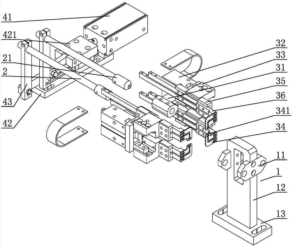
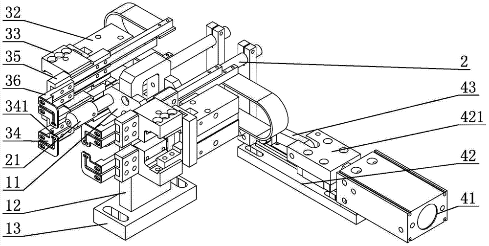
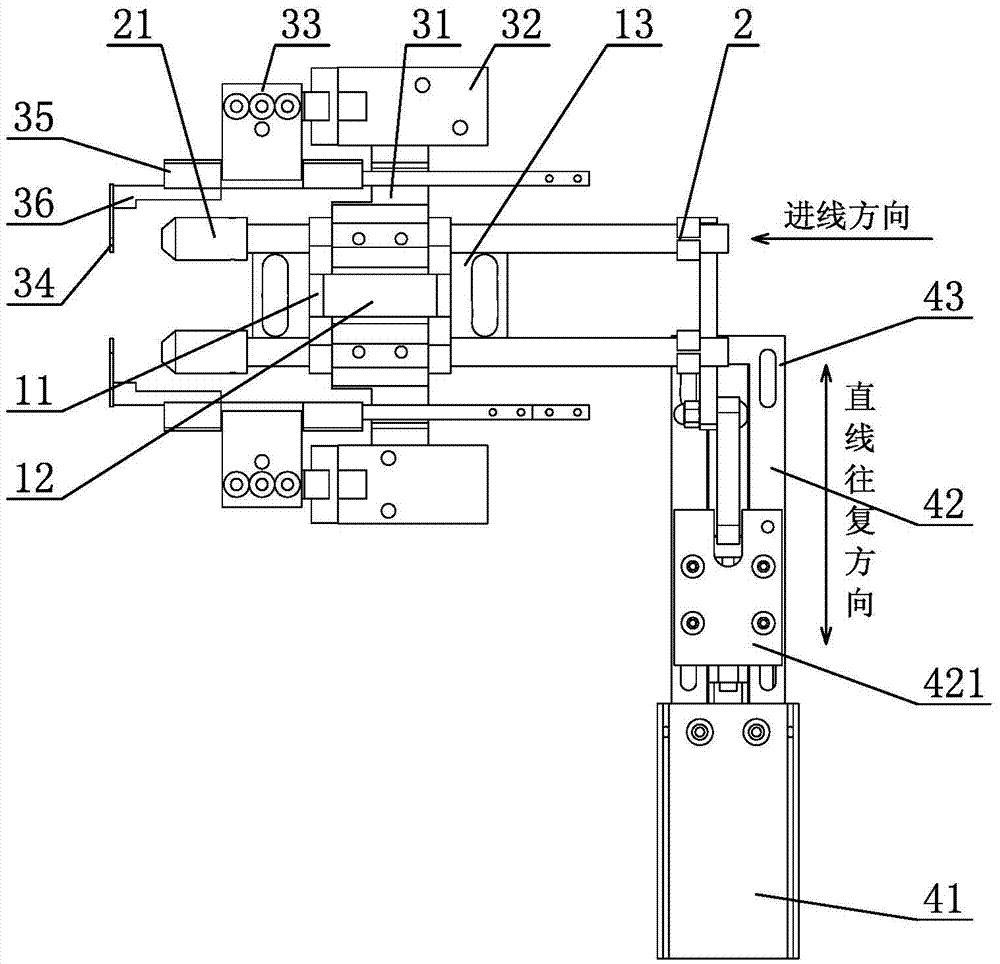
[0021] see Figure 1-Figure 3 , the thermal wire stripping device includes a support base 1, the support base 1 is provided with a wire mechanism 2 for conveying electric wires, and the head end of the corresponding wire mechanism 2 is provided with a wire ironing mechanism for clamping the wire skin of the wire and scalding, and the wire The tail end of the mechanism 2 is connected with a rotating device that drives the wire to rotate back and forth. The head end of the wire mechanism 2 is the wire transmission end, and the tail end is the wire delivery end; the head end of the wire mechanism 2 outputs the wire, and the ironing mechanism clamps the wire And when scalding, the rotating device drives the wire mechanism 2 to drive the electric wire to rotate back and forth, so that the wire skin of the electric wire is evenly heated and fused at 360 degre...


PUM


Abstract

The invention relates to a thermal wire stripping apparatus which includes a supporting pedestal which is provided with a wire mechanism and a wire scalding mechanism. The wire mechanism is intended for transporting an electrical wire. The wire scalding mechanism is disposed at a position corresponding to the head end of the wire mechanism, and is intended for clamping a wire sheath of the electrical wire and conducting thermal scalding. The tail end of the wire mechanism is connected to a rotating apparatus which drives the wire mechanism to rotate the electrical wire back and forth. The head end of the wire mechanism is an electrical wire output end, and the tail end is and an electrical wire input end. When the head end of the wire mechanism outputs an electrical wire, and the wire scalding mechanism clamps the electrical wire and thermally scalds the electrical wire, the rotating apparatus drives the wire mechanism to rotate the electrical wire back and forth, such that the wire sheath of the electrical wire is evenly heated at 360 degrees and is fused. According to the invention, the apparatus herein can rotate the electrical wire in the process of thermal stripping, the wire sheath of the electrical wire can be evenly heated at 360 degrees on the wire scalding mechanism and be fused in real sense, thus realizing automatic wire stripping. The apparatus herein has the characteristics of simple design, scientific structure, high automation and excellent wire stripping effects. The apparatus herein can be designated to strip fiber braided wires, can greatly increase production efficiency and is applicable to promotion for enterprises.

Description

technical field [0001] The invention relates to a thermal wire stripping device, in particular to a thermal wire stripping device which can be specially used for fiber braided wires. Background technique [0002] The traditional wire stripping device usually consists of a solid base, an upper knife seat, and a lower knife seat. The traditional method uses a pneumatic cylinder to control the upper and lower knife seats to reciprocate to achieve stripping, but this device is mostly suitable for power cords made of rubber. And for fiber braided wire, because its surface has one more layer of fiber braided net with greater toughness, when peeling with conventional wire stripping device, it is difficult to peel off, and the wire stripping difficulty is very large and the efficiency is generally on the low side. [0003] Although some wire stripping devices are equipped with an electric heating device on the knife seat, which can help to fuse the fiber braided part, however, becau...

Claims


Application Information

Patent Timeline
IPC IPC(8): H02G1/12
CPCH02G1/12H02G1/1275H02G1/1297
Inventor 黄志刚
Owner 黄志刚
Learn More