Crushing mechanism for crushing pipeline debris
A technology for crushing mechanism and debris, applied in the field of crushing mechanism for crushing debris in pipelines, can solve the problems of low crushing efficiency and weak environmental adaptability, and achieve the effect of improving crushing efficiency
- Summary
- Abstract
- Description
- Claims
- Application Information
AI Technical Summary
Problems solved by technology
Method used
Image
Examples
no. 1 example
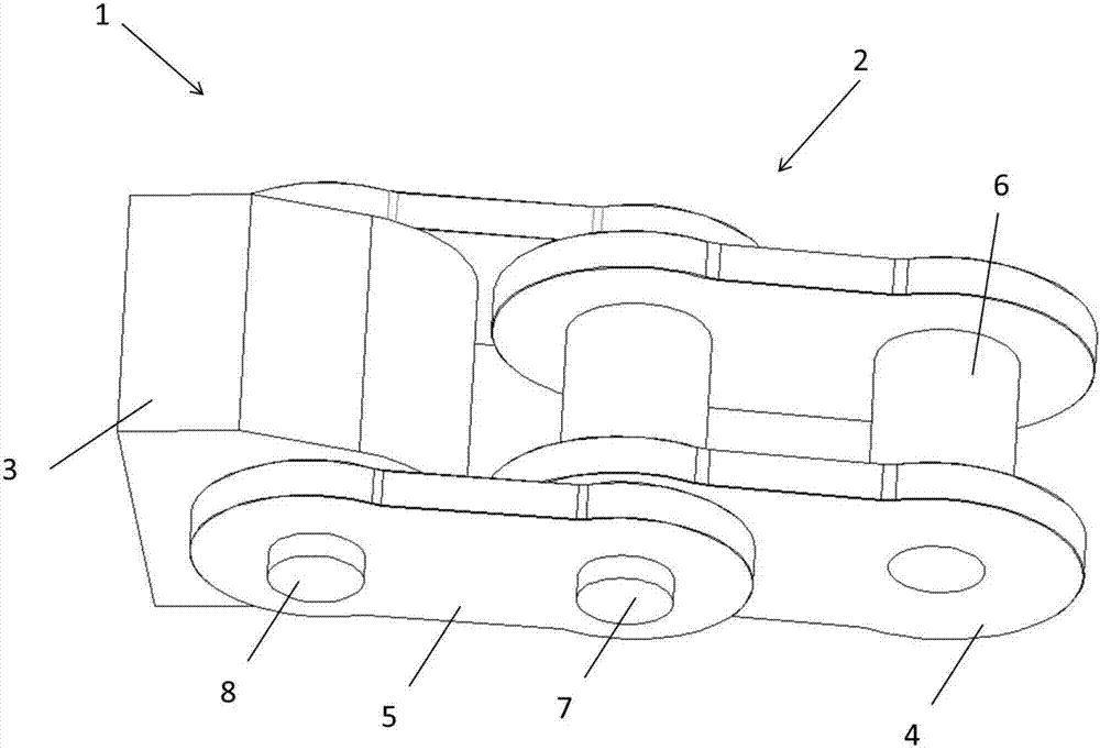
[0024] refer to figure 1 , this embodiment provides a crushing mechanism 1 for crushing pipeline sundries, including a flexible chain 2 and a crushing hammer 3 .
[0025] The chain 2 includes two inner chain plates 4 and two outer chain plates 5 .
[0026] The two inner chain plates 4 are connected by sleeves 6 at both ends.
[0027] One end of the two outer link plates 5 is connected with one end of the two inner link plates 4 , for example, one end of the two outer link plates 5 is connected with one end of the two inner link plates 4 through a pin 7 .
[0028] The crushing hammer 3 is connected to the other ends of the two outer chain plates 5 , for example, the crushing hammer 3 is connected to the other ends of the two outer chain plates 5 through a pin 8 .
[0029] Since the outer chain plate 5 and the inner chain plate 4, the crushing hammer 3 and the outer chain plate 5 are all connected by pin shafts, the outer chain plate 5 and the inner chain plate 4 can rotate re...
no. 2 example
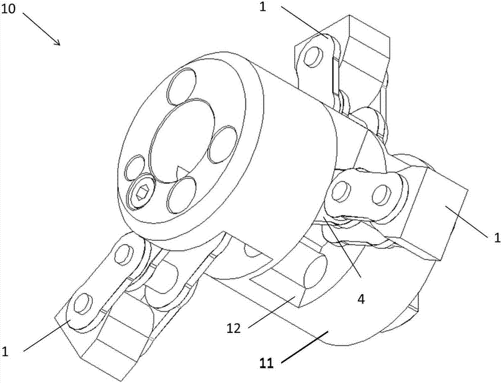
[0035] refer to Figure 2-4 , the present embodiment provides a crushing device 10 for crushing pipeline sundries, including several crushing mechanisms 1 and output shafts 11 described in the first embodiment.
[0036] In this embodiment, the number of crushing mechanisms 1 is three. The pulverizing mechanism 1 is used for pulverizing sundries in the pipeline.
[0037] The pulverizing mechanism 1 is arranged on the output shaft 11, and the output shaft 11 drives the pulverizing mechanism 1 to rotate to pulverize sundries.
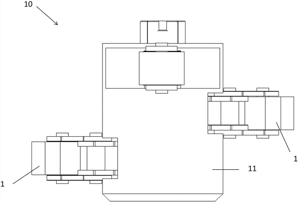
[0038] refer to image 3 The crushing mechanism 1 is arranged on the output shaft 11 at equal intervals along the axial direction of the output shaft 11 .
[0039] image 3 Only two crushing mechanisms 1 are shown in the figure, and the other crushing mechanism 1 is blocked by the output shaft 11.
[0040] refer to Figure 4 The crushing mechanism 1 is arranged on the output shaft 11 at equal intervals along the circumferential direction of the outpu...
no. 3 example
[0046] refer to Figure 5 , the present embodiment provides a pipe debris crushing device 100 , including a support 101 , an adsorption baffle 102 , an end cover 103 , a connecting plate 104 , an output shaft 11 and a crushing mechanism 1 .
[0047] Wherein, the adsorption baffle 102 is fixedly connected with the support 101 and is located inside the support 101 . More specifically, a hole is opened in the center of the adsorption baffle 102, which is suitable for allowing the support 101 to pass through.
[0048] The inner side of the support 101 refers to the side close to the end cover 103 .
[0049] The support 101 and the adsorption baffle 102 are circular, the centers of the support 101 and the adsorption baffle 102 are aligned, and the diameter of the support 101 is smaller than the diameter of the adsorption baffle 102 .
[0050] The support 101 and the adsorption baffle 102 are fixedly connected by screws.
[0051] Described end cap 103 is arranged in parallel with...
PUM
 Abstract
Description
Claims
Application Information
 - R&D
- Intellectual Property
- Life Sciences
- Materials
- Tech Scout
- Unparalleled Data Quality
- Higher Quality Content
- 60% Fewer Hallucinations
Browse by: Latest US Patents, China's latest patents, Technical Efficacy Thesaurus, Application Domain, Technology Topic, Popular Technical Reports.
© 2025 PatSnap. All rights reserved.Legal|Privacy policy|Modern Slavery Act Transparency Statement|Sitemap|About US| Contact US: help@patsnap.com


