
Installation device of sliding plug door system of multiple-unit train

A system installation and EMU technology, applied in the field of EMU plug door system installation device, can solve the problems of low installation accuracy and installation efficiency, and achieve the effects of improved installation accuracy and installation efficiency, and enhanced practicability and versatility

Active Publication Date: 2017-07-28
CRRC CHANGCHUN RAILWAY VEHICLES CO LTD
View PDF12 Cites 7 Cited by
  • Summary
  • Abstract
  • Description
  • Claims
  • Application Information

AI Technical Summary

Problems solved by technology

[0005] In order to solve the technical problems of low installation accuracy and low installation efficiency in the existing single-piece multiple installation methods, the invention provides an installation device for the sliding door system of EMUs

Method used


Image

  • Installation device of sliding plug door system of multiple-unit train
  • Installation device of sliding plug door system of multiple-unit train
  • Installation device of sliding plug door system of multiple-unit train

Examples


Embodiment Construction

[0037] The present invention will be described in further detail below in conjunction with the accompanying drawings.

[0038] like Figure 4 to Figure 17 As shown, the EMU plug door system installation device of the present invention includes: a movable door frame clamping mechanism 2, a driving mechanism height positioning mechanism 3, a vehicle body upper positioning mechanism 4, a vehicle body lower positioning mechanism 5 and an equipment rack mounting mechanism 6.

[0039] The movable door frame clamping mechanism 2 includes a rectangular frame 2-1, a door frame conformal support structure 2-2, a plurality of clamps 2-3 on both sides of the door frame, two upper columns 2-4, two lower columns 2-5, Two side clamps 2-6, two upper body clamps 2-7, two lower body clamps 2-8, two door frame upper quick clamps 2-9, two door frame uppers Support 2-10, two door frame lower quick clamps 2-11, two door frame lower supports 2-12, two upper quick clamps 2-13, two upper positioning ...


PUM


Abstract

The invention belongs to the technical field of precise installation of sliding plug door systems of passenger trains and provides an installation device of a sliding plug door system of a multiple-unit train. The installation device of the sliding plug door system of the multiple-unit train comprises a movable door frame clamping mechanism, a drive mechanism height locating mechanism, a train body internal upper locating mechanism, a train body internal lower locating mechanism and an equipment frame installing mechanism, wherein the movable door frame clamping mechanism is used for clamping and fixing a movable door frame of a sliding plug door, the drive mechanism height locating mechanism is used for conducting height locating on a drive mechanism of the sliding plug door, the train body internal upper locating mechanism is used for installing and locating the upper portion of the movable door frame clamping mechanism, the train body internal lower locating mechanism is used for installing and locating the lower portion of the movable door frame clamping mechanism, and the equipment frame installing mechanism is used for installing and locating an equipment frame of the sliding plug door. By the adoption of the installation device of the sliding plug door system of the multiple-unit train, one-time installing and locating of the sliding plug door system can be achieved, and the installation precision and the installation efficiency are both improved; the movable door frame clamping mechanism and the equipment frame installing mechanism are both of a bilateral symmetry structure, the function that the sliding plug door system on the left side and the right side are located and installed through one device can be achieved through structural matching of the equipment frame installing mechanism and the movable door frame clamping mechanism, and the practicability and the universality are improved.

Description

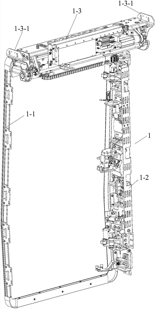
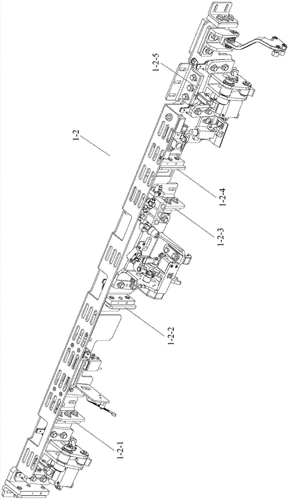
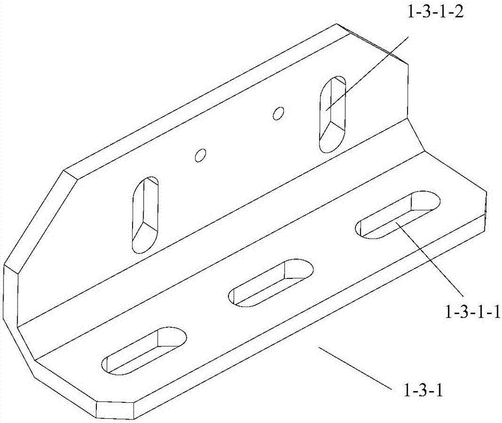
Technical field [0001] The invention belongs to the technical field of precision installation of railway passenger car plug door systems, and specifically relates to an EMU plug door system installation device. Background technique [0002] like Figure 1 to Figure 3 As shown, the plug door system 1 of the existing domestic EMU includes a movable door frame 1-1, a door panel (not shown in the figure) embedded in the movable door frame 1-1, an equipment rack 1-2 and a driving mechanism 1-3 , the driving mechanism hanger 1-3-1 is connected to the vehicle body through the longitudinal long hole 1-3-1-2, and the driving mechanism 1-3 is connected to the driving mechanism hanger 1 through the transverse long hole 1-3-1-1 -3-1 connection. During installation, it is necessary to ensure the spatial position and cooperative relationship between the movable door frame 1-1, the equipment rack 1-2 and the driving mechanism 1-3 to avoid vehicle sealing due to inaccurate installation pos...

Claims


Application Information

Patent Timeline
IPC IPC(8): B23P21/00
CPCB23P21/00Y02T30/00
Inventor 徐岩曲双宋娇
Owner CRRC CHANGCHUN RAILWAY VEHICLES CO LTD
Learn More