
A new fan with automatic control function

A new fan, functional technology, applied in the field of air purification, can solve the problems of increased cost, complex structure, damage to the heat exchange core, etc., to achieve the effect of prolonging the service life, high air purification rate, and improving applicability

Active Publication Date: 2020-06-19
KUNSHAN SILAIMU ENERGY SAVING TECH CO LTD
View PDF8 Cites 0 Cited by
  • Summary
  • Abstract
  • Description
  • Claims
  • Application Information

AI Technical Summary

Problems solved by technology

[0004] Some fresh air fans of this type currently on the market have complex structures, unreasonable layouts, and are inconvenient to use. They also use aluminum heat exchange cores. After a period of operation, condensation water will form on the surface of the aluminum heat exchange cores, which will affect heat exchange. The working effect of the core body may even damage the heat exchange core body and shorten the service life of the fresh air machine. Complicated; In addition, some of the above-mentioned fresh air fans sold on the market do not have filter elements at the indoor return air outlets, and the polluting particles contained in the indoor return air enter the heat exchange core, which is easy to damage the heat exchange core and shorten the service life of the ceiling-type fresh air fan. service life
[0005] In addition, most of the existing fresh air fans of this type only continue to run in the operating mode selected by people when they are turned on, and do not have the function of automatically adjusting the operating mode of the fresh air fan according to the data changes of pollutants in the air, and cannot adapt to people's various needs. The need to purify polluted air is not conducive to people's health

Method used


Image

  • A new fan with automatic control function
  • A new fan with automatic control function
  • A new fan with automatic control function

Examples


Embodiment

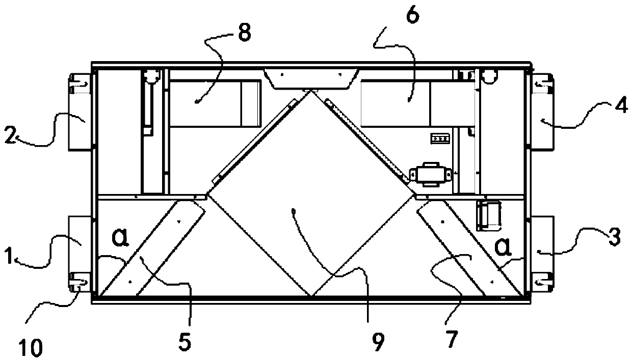
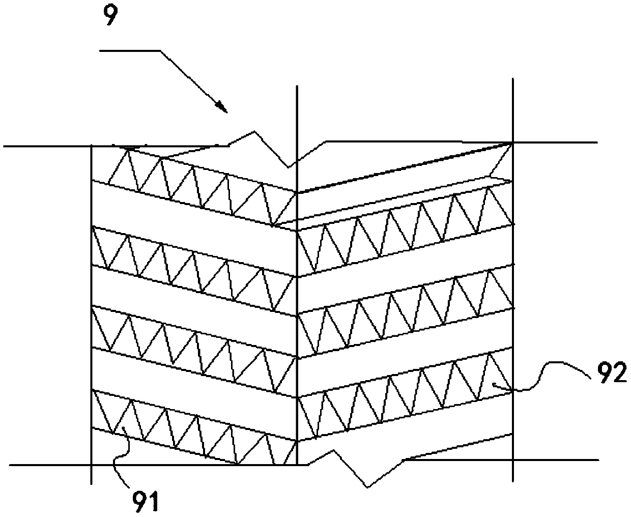
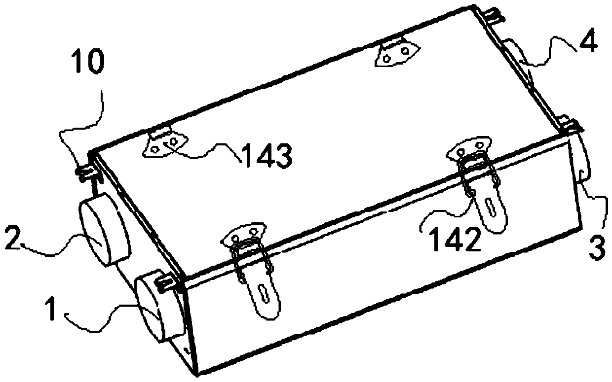
[0051] Embodiment: a kind of fresh fan with automatic control function, as Figure 1-5 As shown, it includes a casing, an outdoor air inlet 1, an outdoor air outlet 2, an indoor return air outlet 3 and an indoor air supply outlet 4. The outdoor air outlet 2 and the outdoor air inlet 1 are respectively located at the At the left end, the indoor air return port 3 and the indoor air supply port 4 are respectively located at the right end of the housing;

[0052] A fresh air channel and a return air channel are intersected in the housing, and the two ends of the fresh air channel are respectively provided with a fresh air filter 5 and an air inlet fan 6, and the fresh air filter 5 communicates with the outdoor air inlet 1, so that The air inlet fan 6 communicates with the indoor air supply port 4, and one end of the air return channel is provided with a return air fan 8, and the return air fan 8 communicates with the outdoor air outlet 2, and the return air channel The other end ...


PUM


Abstract

The invention discloses a fresh air fan with an automatic control function, which comprises a shell, an outdoor air inlet, an outdoor air exhaust port, an indoor air return port and an indoor air supply port. The two ends are respectively connected with the fresh air filter and the air inlet fan, the fresh air filter is connected with the outdoor air inlet, the air inlet fan is connected with the indoor air supply port, and the two ends of the return air passage are respectively connected with the indoor return air outlet and the return air fan, and the return air fan is connected with the indoor air supply port. The indoor air return port is connected, and the intersection of the fresh air channel and the return air channel is provided with a heat exchange core; a PLC controller, an environmental monitoring module and an external control panel are also provided. The present invention has the function of temperature and humidity in the air, CO 2 , PM2.5 and VOC are monitored, and then the corresponding operation mode is automatically adjusted according to the monitoring data, which has a high degree of automation, improves the purification effect of the fresh air purifier, and is convenient for people to use.

Description

technical field [0001] The invention relates to the technical field of air purification, in particular to a new fan with automatic control function. Background technique [0002] With the continuous progress of industrial automation and the continuous improvement of people's quality of life, people's requirements for their living environment are also constantly improving, and air quality is an important symbol of the quality of the environment, which directly affects people's healthy life. The smog and dust in the air, coupled with the environmental pollution caused by interior decoration, has become a social problem. These polluting gases have been scientifically proven to have a great impact on the human body, and can easily lead to respiratory diseases, cancer, Leukemia and neurological diseases are especially harmful to pregnant women, children and the elderly. Therefore, it is very important for the purification of indoor air. [0003] The fresh air fan equipped with ...

Claims


Application Information

Patent Timeline
Patent Type & Authority Patents(China)
IPC IPC(8): F24F3/16F24F12/00F24F11/63F24F11/89F24F13/28F24F110/10F24F110/20F24F110/64F24F110/65F24F110/70F24F8/108
CPCF24F11/62F24F2110/20F24F2110/50F24F11/89F24F11/30F24F2110/10F24F12/006F24F13/28F24F2110/70F24F2110/64F24F11/58F24F2110/66F24F8/108F24F8/10Y02B30/56Y02B30/70
Inventor 戴文朱蓓蕾薛健
Owner KUNSHAN SILAIMU ENERGY SAVING TECH CO LTD
Learn More