Cylindricity detection device for brake clutch plate production

A technology for detection devices and clutch discs, applied in the direction of measuring devices, mechanical devices, mechanical measuring devices, etc., can solve the problems of poor detection results, large detection errors, time-consuming and labor-intensive problems, etc.

Inactive Publication Date: 2017-07-28
邱艳
View PDF7 Cites 7 Cited by
  • Summary
  • Abstract
  • Description
  • Claims
  • Application Information

AI Technical Summary

Problems solved by technology

[0006] In order to overcome the shortcomings of manual detection of the cylindricity of the brake clutch plate, the detection effect is not good, and time-consuming and labor-intensive, the technical problem to be solved by the present invention is to provide a method that can reduce errors, improve detection effects, and can Time-saving and labor-saving cylindricity detection device for brake clutch plate production

Method used


Image

  • Cylindricity detection device for brake clutch plate production
  • Cylindricity detection device for brake clutch plate production
  • Cylindricity detection device for brake clutch plate production

Examples


Embodiment 1

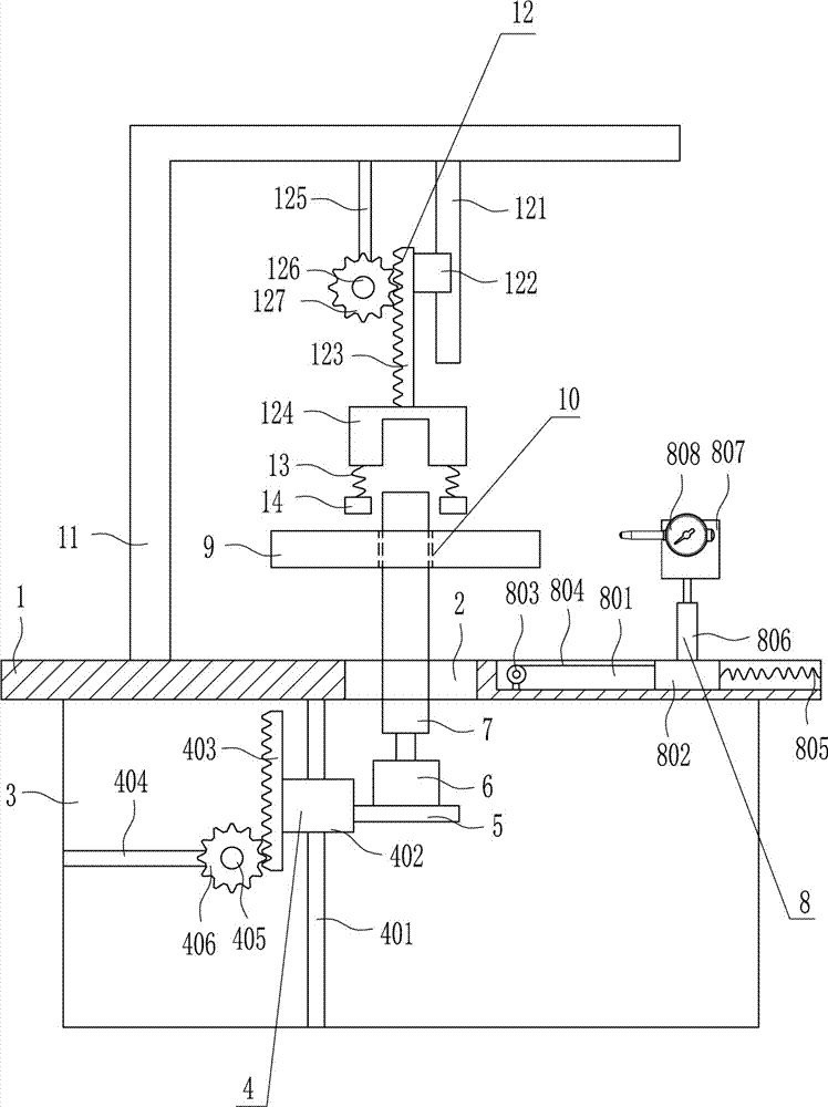
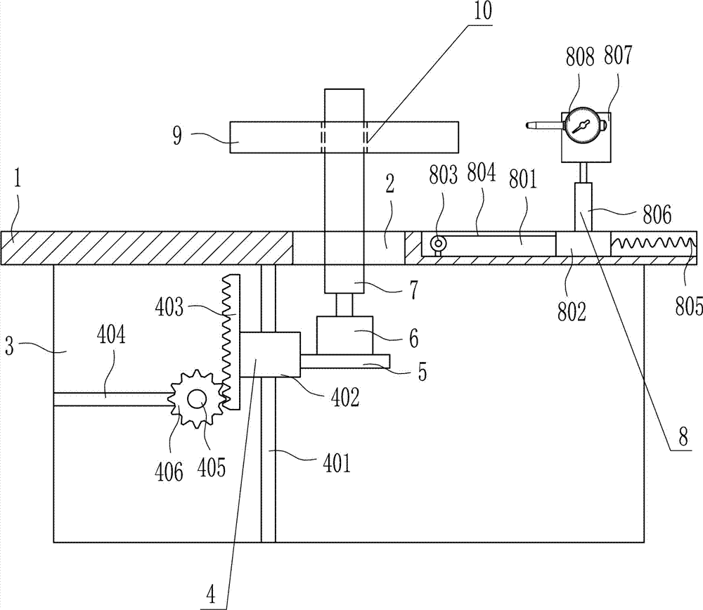
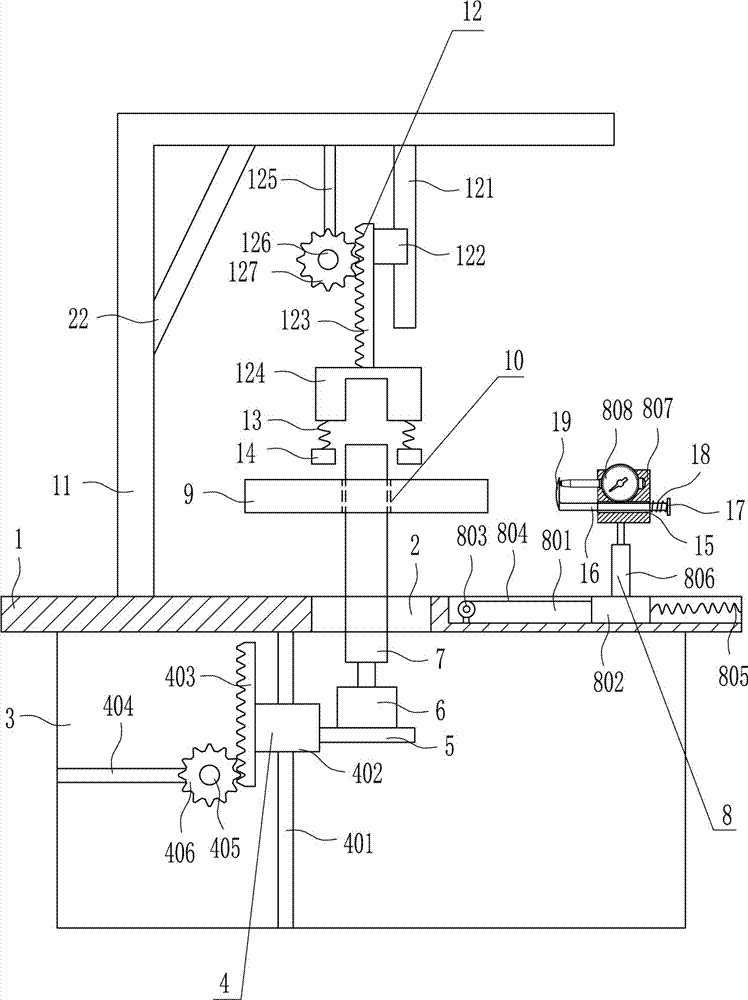
[0038] A cylindricity detection device for the production of brake clutch discs, such as Figure 1-7 As shown, it includes a desktop 1, a hollow table 3, an up and down movement mechanism 4, a support plate 5, a first motor 6, a hollow pole 7 and a detection device 8. There is an opening 2 in the middle of the top of the desktop 1, and the bottom of the desktop 1 The hollow table 3 is connected by bolts, the hollow table 3 is provided with an up and down movement mechanism 4, the moving part of the up and down movement mechanism 4 is connected with a support plate 5, the top of the support plate 5 is equipped with a first motor 6 through bolts, and The output shaft of a motor 6 is connected with a hollow strut 7 through a coupling, and the hollow strut 7 cooperates with the brake clutch plate 9, and the top of the desktop 1 on the right side of the opening 2 is provided with a detection device 8.

Embodiment 2

[0040] A cylindricity detection device for the production of brake clutch discs, such as Figure 1-7 As shown, it includes a desktop 1, a hollow table 3, an up and down movement mechanism 4, a support plate 5, a first motor 6, a hollow pole 7 and a detection device 8. There is an opening 2 in the middle of the top of the desktop 1, and the bottom of the desktop 1 The hollow table 3 is connected by bolts, the hollow table 3 is provided with an up and down movement mechanism 4, the moving part of the up and down movement mechanism 4 is connected with a support plate 5, the top of the support plate 5 is equipped with a first motor 6 through bolts, and The output shaft of a motor 6 is connected with a hollow strut 7 through a coupling, and the hollow strut 7 cooperates with the brake clutch plate 9, and the top of the desktop 1 on the right side of the opening 2 is provided with a detection device 8.

[0041] The up and down movement mechanism 4 includes a slide bar 401, a sliding...

Embodiment 3

[0043] A cylindricity detection device for the production of brake clutch discs, such as Figure 1-7 As shown, it includes a desktop 1, a hollow table 3, an up and down movement mechanism 4, a support plate 5, a first motor 6, a hollow pole 7 and a detection device 8. There is an opening 2 in the middle of the top of the desktop 1, and the bottom of the desktop 1 The hollow table 3 is connected by bolts, the hollow table 3 is provided with an up and down movement mechanism 4, the moving part of the up and down movement mechanism 4 is connected with a support plate 5, the top of the support plate 5 is equipped with a first motor 6 through bolts, and The output shaft of a motor 6 is connected with a hollow strut 7 through a coupling, and the hollow strut 7 cooperates with the brake clutch plate 9, and the top of the desktop 1 on the right side of the opening 2 is provided with a detection device 8.

[0044] The up and down movement mechanism 4 includes a slide bar 401, a sliding...


PUM


Abstract

The invention relates to a brake clutch plate detection device and especially relates to a cylindricity detection device for brake clutch plate production. The technical problem to be solved by the invention is to provide a brake clutch plate production cylindricity detection device, which can reduce errors, improve detection effect and can save time and labor. In order to solve the technical problem, the invention provides the cylindricity detection device for brake clutch plate production. The cylindricity detection device comprises a desktop, a hollow table, an up-down moving mechanism, a support board and a first motor and the like. The top portion of the desktop is provided with an opening in the center; the bottom portion of the desktop is connected with the hollow table through a bolt; the hollow table is internally provided with the up-down moving mechanism; and a mobile component of the up-down moving mechanism is connected with the support board. The device realizes cylindricity detection of a brake clutch plate through a detection device and enables the brake clutch plate to be always in a horizontal state through a first fixation device and a second fixation device, so that errors can be reduced.

Description

technical field [0001] The invention relates to a detection device for a brake clutch plate, in particular to a cylindricity detection device for the production of a brake clutch plate. Background technique [0002] The clutch plate is a vulnerable part in the driving system of a motor vehicle. When using it, special attention should be paid to not keeping your feet on the clutch pedal when the engine is running. [0003] Braking, also known as braking, refers to the action of stopping or reducing the speed of running locomotives, vehicles and other means of transportation or machinery. The general principle of braking is to fix a wheel or disc on the high-speed shaft of the machine, install a corresponding brake shoe, belt or disc on the machine base, and make it generate braking torque under the action of external force. The brake device is also a mechanical brake device that can slow down the speed of the vehicle, also known as a reducer. To put it simply: the brake ped...

Claims


Application Information

Patent Timeline
Patent Type & Authority Applications(China)
IPC IPC(8): G01B5/20
CPCG01B5/201
Inventor 不公告发明人
Owner 邱艳
Why Eureka
Try Eureka