A level shift circuit

A technology of level shifting circuits and core circuits, which is applied in the connection/interface layout of logic circuits, coupling/interfaces of logic circuits using field effect transistors, etc. Reduce, speed up conversion speed, reduce the effect of conversion delay

Inactive Publication Date: 2019-01-29
UNIV OF ELECTRONICS SCI & TECH OF CHINA
View PDF4 Cites 0 Cited by
  • Summary
  • Abstract
  • Description
  • Claims
  • Application Information

AI Technical Summary

Problems solved by technology

[0003] The purpose of the present invention is to solve the problems of large power consumption and large propagation delay in the existing level shifting circuit, and propose a level shifting circuit

Method used


Image

  • A level shift circuit
  • A level shift circuit
  • A level shift circuit

Examples


Embodiment Construction

[0024] Below in conjunction with accompanying drawing, describe technical scheme of the present invention in detail:

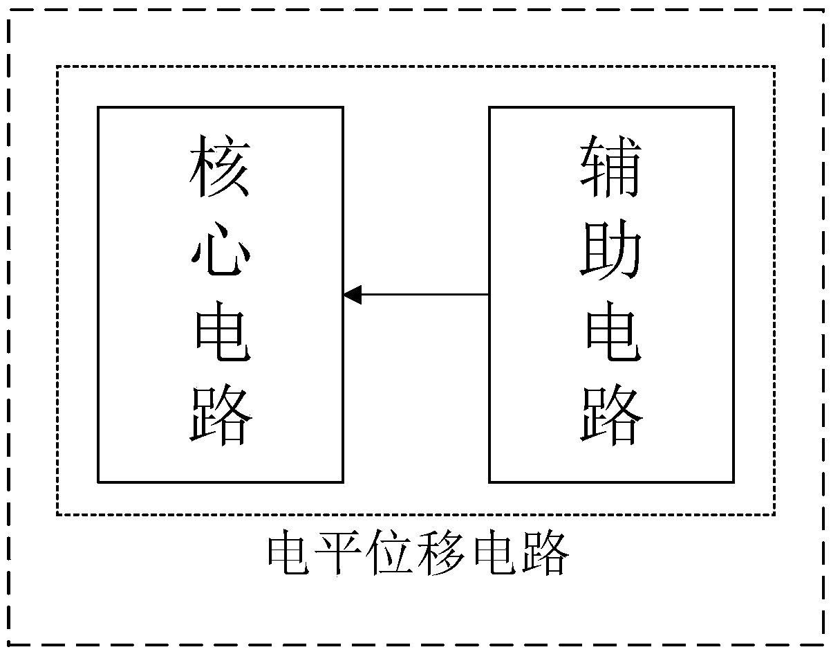
[0025] figure 2 It is a circuit block diagram of the present invention. As shown in the figure, an auxiliary circuit module is added to the level shift of this solution to further reduce the conversion delay time and power consumption.

[0026] The working principle of the present invention is:

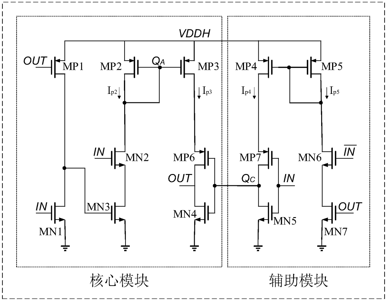
[0027] Core circuit: The function of the core circuit is to realize the conversion of low-high and high-low working voltage.

[0028] like image 3 As shown, when the input signal IN changes from low to high, the output signal OUT is still low because the output signal OUT cannot respond to the input signal in time, and the first PMOS transistor MP1 is still turned on at this time, because the overdrive voltage of the first PMOS transistor is greater than the overdrive voltage of the first NMOS transistor MN1, so the third NMOS transistor MN3 is still turned on. ...


PUM


Abstract

The invention belongs to the technical field of integrated circuits, relates to a MOS grid drive circuit, and specifically relates to a level shifting circuit. Relative to a common level shifting circuit, a first PMOS tube MP1, a second PMOS tube MP2, a third PMOS tube MP3, a first NMOS tube NM1, a second NMOS tube NM2, a third NMOS tube NM3, a sixth PMOS tube MP6, and a fourth NMOS tube NM4 are used for forming the level shifting circuit in the scheme provided by the invention; in combination with an auxiliary module circuit, on the one hand, the power consumption is reduced, on the other hand, the conversion speed can be accelerated, and the conversion delay is lowered.

Description

technical field [0001] The invention belongs to the technical field of integrated circuits and relates to a MOS gate drive circuit, in particular to a level shift circuit. Background technique [0002] In some medium-speed digital-analog mixed-signal circuits and digital circuits, different modules work at different speeds. These circuits have introduced "dual drive" to ensure that some non-critical modules can work at low voltage, while the other part is analog and high-speed digital modules capable of operating at high voltages. In order to realize "dual driving", the level shifting circuit needs to be used to convert the lower logic level to a higher logic level to make the next stage module work normally. Traditional level shifting circuits (such as figure 1 As shown), there are problems that the level below the threshold cannot be converted, the conversion power consumption is large, and the propagation delay time is large. Therefore, level-shifting circuit power con...

Claims


Application Information

Patent Timeline
Patent Type & Authority Patents(China)
IPC IPC(8): H03K19/0185
CPCH03K19/0185
Inventor 方健陈智昕张波方舟
Owner UNIV OF ELECTRONICS SCI & TECH OF CHINA
Why Eureka
Try Eureka