Pipe body punching device

A punching device and pipe body technology, applied in the field of machinery, can solve the problems of inconvenience, inability to scale continuous punching, etc., and achieve the effect of continuous automatic operation

Inactive Publication Date: 2017-08-01
TAIZHOU YUANDA HOME FURNITURE CO LTD
View PDF7 Cites 2 Cited by
  • Summary
  • Abstract
  • Description
  • Claims
  • Application Information

AI Technical Summary

Problems solved by technology

[0002] In the process of mechanical processing, the drilling of the pipe body can only be done manually one by one, and it cannot be drilled continuously on a large scale, which brings some inconvenience to the user.

Method used


Image

  • Pipe body punching device

Examples


Embodiment Construction

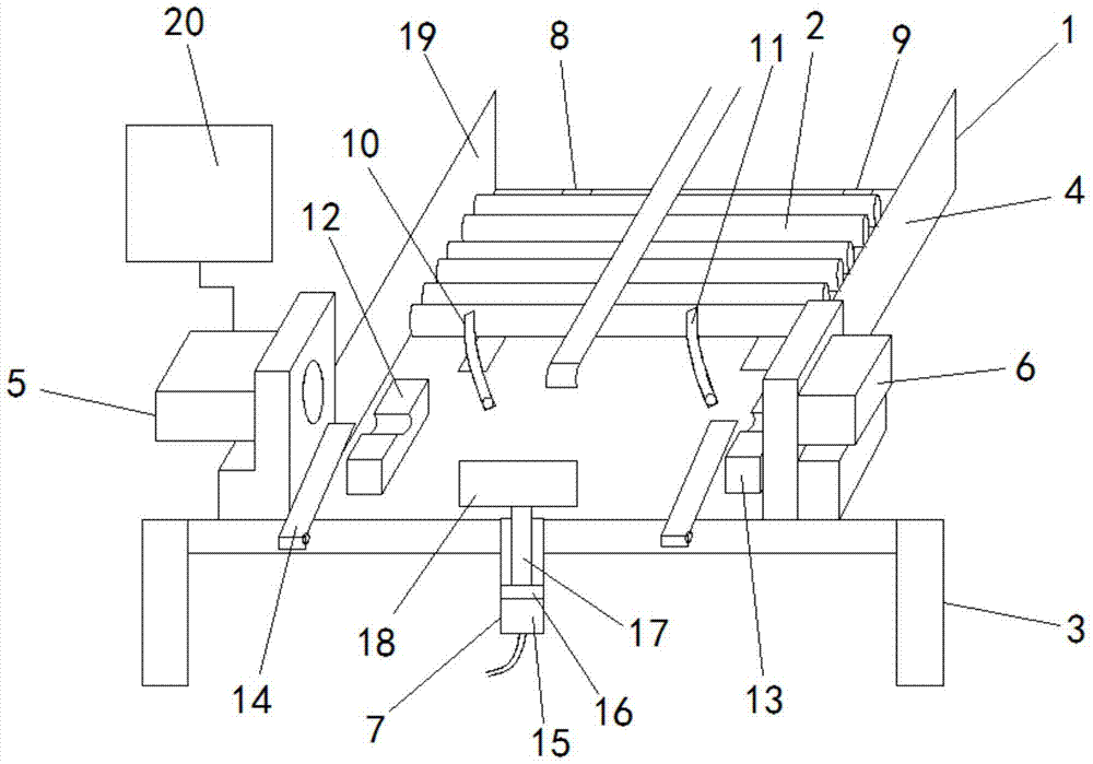
[0012] In order to make the object, technical solution and advantages of the present invention clearer, the implementation manner of the present invention will be further described in detail below in conjunction with the accompanying drawings.

[0013] Such as figure 1 As shown, in the first embodiment of the pipe body punching device of the present invention, the pipe body 2 punching device 1 is used to punch holes at both ends of the pipe body 2, and the punching device 1 includes a support table 3, and the support The platform 3 is fixedly connected to the slope platform 4, and the connection between the two sides of the support platform 3 and the slope platform 4 is respectively equipped with a first puncher 5 and a second puncher 6, and the support platform 3 is provided with the From the pipe body 2 to the pneumatic conveying device 7 at the position of the first puncher 5 and the second puncher 6, the slope platform 4 is provided with a first guide bar 8 and a second gu...


PUM


Abstract

The invention discloses a pipe body punching device, which is used for punching holes at both ends of a pipe body. The punching device includes a support platform and a slope platform fixedly connected with the support platform. A first hole puncher and a second hole puncher are respectively provided at the joint, and a pneumatic conveying device is provided on the support platform to convey the pipe body upwards to the positions of the first hole puncher and the second hole puncher. A first guide bar and a second guide bar arranged parallel to each other are provided on the top, a first stop block is provided at the end of the first guide bar to block the pipe body, and at the end position of the second guide bar A second stop block is provided to block the pipe body, a first motor that drives the first stop block and the second stop block to rotate is provided in the ramp platform, and a position below the first guide bar is provided for The pipe body is conveyed to the first conveying block on the pneumatic conveying device, and a second conveying block for conveying the pipe body to the pneumatic conveying device is arranged at a position below the second guide slide bar.

Description

technical field [0001] The invention relates to the mechanical field, more specifically, to a pipe body punching device. Background technique [0002] In the process of mechanical processing, the holes on the pipe body can usually only be manually operated one by one, and the holes cannot be drilled continuously on a large scale, which brings some inconvenience to the user. Contents of the invention [0003] The technical problem to be solved by the present invention is to provide a pipe body punching device aiming at the above-mentioned defects of the prior art. [0004] The technical scheme adopted by the present invention to solve the technical problem is: construct a pipe body punching device for punching holes at both ends of the pipe body, the punching device includes a support platform, a slope platform fixedly connected with the support platform, A first punching machine and a second punching machine are respectively provided at the connection between the two side...

Claims


Application Information

Patent Timeline
Patent Type & Authority Applications(China)
IPC IPC(8): B21D28/28B21D43/16
CPCB21D28/28B21D43/006B21D43/16
Inventor 陈晓先张忠华
Owner TAIZHOU YUANDA HOME FURNITURE CO LTD
Why Eureka
Try Eureka