River garbage automatic drifting separator

A technology for separators and garbage, applied in water conservancy projects, cleaning of open water surfaces, construction, etc., can solve pollution, serious problems, etc., and achieve the effect of high separation cleanliness and fast efficiency

Inactive Publication Date: 2008-03-05
李德兴
View PDF0 Cites 2 Cited by
  • Summary
  • Abstract
  • Description
  • Claims
  • Application Information

AI Technical Summary

Problems solved by technology

[0002] Due to the continuous increase of all kinds of garbage, the pollution of rivers and

Method used


Image

  • River garbage automatic drifting separator
  • River garbage automatic drifting separator
  • River garbage automatic drifting separator

Examples


Embodiment Construction

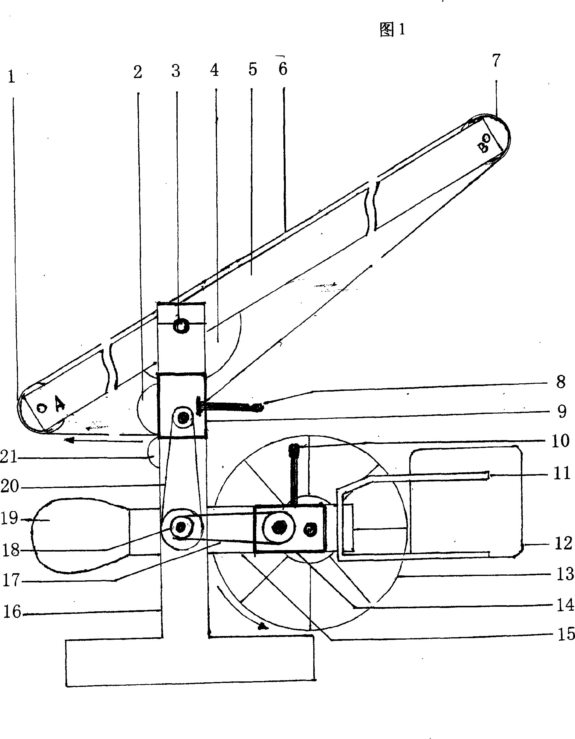
[0016] Illustrate implementation of the present invention below with reference to accompanying drawing

[0017] Axle 18 is arranged on column 16 to link horizontal frame 15 and column 16 together, and horizontal frame 15 can rotate flexibly on axis 18. One end of cross frame 15 has water wheel 13 to provide power for separator, and clutch 14 and transmission chain 17 are arranged on the axle of water wheel 13, can play the power effect of separation, transmission water wheel 13. The power transmission and separation between the water wheel 13 and the transmission chain 17 can be done through the operating lever 10 . There is buoyant tank 12 installed on the buoyant tank frame 11 at the back of waterwheel 13, and buoyant tank 12 can drive waterwheel 13 to float up and down together with the fluctuation of water level.

[0018] There is a balance bar 19 at the other end of the cross frame 15, and the balance rod 19 is to keep the balance between the two ends of the cross frame ...


PUM


Abstract

The automatic river garbage floating and separating machine as one kind of river water environment tackling apparatus includes one frame, one rotating water mill, one floating tank, one separator, one control box for controlling the elevation of the separator, one row of flat rods for collecting the garbage in water, one row of floating rods for collecting floated garbage, and other parts. It is set in river, and under the action of water flow, it separates and collects garbage from water flow.

Description

Technical field: [0001] The invention relates to a treatment facility for the water environment of rivers and ditches, and an automatic drift-separation machine for river course garbage. Background technique: [0002] Due to the continuous increase of various garbage now, the pollution of rivers and ditches is becoming more and more serious, and there is no better way to solve this problem now. Invention content: [0003] The purpose of the present invention is to design an automatic drifting separator for river garbage, which uses the power generated by the water wheel to drive the separator to drive the separator, and the garbage in the river is gathered to one side of the separator by the drifting rod for the running The special separator separates the garbage from the bottom of the water to the surface of the water and sends it to the river bank. The machine can realize unmanned operation and continuous automatic operation around the clock. [0004] The object of the...

Claims


Application Information

Patent Timeline
IPC IPC(8): E02B15/04
Inventor 李德兴
Owner 李德兴
Why Eureka
Try Eureka