Static contact with homing system for isolation switch

A technology of isolating switch and static contact, applied in electrical switches, air switch parts, high-voltage air circuit breakers, etc., can solve the problems of inability to return, difficult to maintain, poor weather resistance, etc. Long-term use, novel and unique effect

Inactive Publication Date: 2017-08-01
林向阳
0 Cites 3 Cited by

AI-Extracted Technical Summary

Problems solved by technology

[0003] First, long-term operation will inevitably lead to a certain deformation of the static contact, resulting in uneven pressure, which will not ensure reliable contact between the moving contact and the static contact, and will more easily cause spark discharge, thus forming a vicious circle;
[0004] Second, using the electromagnetic force generated by circular current and Ampere's law to make the electromagnetic sheet of the static contact tighten the moving contact is easy to damage and is not suitable for long-term use; when the current flows through the bent The electromagnetic sheets each generate a magnetic field, and the repulsive force in a single electromagnetic sheet will cause the electromagnetic sheet to deform. If things go on like this, it will not be able to return to its position, and thus cannot be use...

Method used

As shown in Figure 1-3, a kind of isolating switch static contact with homing system, comprises fixed head 1, also comprises conductive splint 2 and is arranged on the root of conductive splint 2 and slides with conductive splint 2 Coordinated homing system, the homing system includes a homing piece 4 sleeved on the conductive splint 2, a spring 5, and a limiting boss on the conductive splint 2 for limiting the limit position of the horizontal movement of the homing piece 4 7 and the guide sleeve 8 fixedly arranged on the outside of the conductive splint 2, the root of the guide sleeve 8 is extended and connected in the fixed head 1, which consolidates the stability. As shown in Figure 2, the return part 4 is provided with a supply The jack 9 into which the conductive splint 2 is inserted, and the jack 9 is respectively extended to two ends to be provided with a track slot 10 for the conductive splint 2 to slide back and forth. The width of the track slot 10 is not less than the width of the jack 9. A spring 5 is connected between t...

Abstract

The invention relates to a static contact with a homing system for an isolation switch. The stator contact comprises a fixed head and also comprises a conductive sandwiched plate and the homing system, wherein the homing system is arranged at a root of the conductive sandwiched plate and is matched with the conductive sandwiched plate in a sliding way, the homing system comprises a homing piece, a spring, a limitation boss and a guide sleeve, the homing piece sleeves the conductive sandwiched plate, the limitation boss is arranged on the conductive sandwiched plate and is used for limiting a horizontal movement limit position of the homing piece, and the guide sleeve is fixedly arranged at an outer part of the conductive sandwiched plate. The static contact with the homing system for the isolation switch is novel and unique in design, simple and efficient in structure, good in performance and low in construction cost, more importantly, the static contact has a homing function, the action limitation during usage and automatic homing after usage of the static contact are ensured, deformation and excessive damage caused by changes of a current and an electromagnetic force are prevented, the static contact is convenient to use for a long time and is convenient to maintain, and the static contact has good application prospect.

Application Domain

Air-break switch details

Technology Topic

StatorEngineering +2

Image

  • Static contact with homing system for isolation switch
  • Static contact with homing system for isolation switch
  • Static contact with homing system for isolation switch

Examples

  • Experimental program(1)

Example Embodiment

[0026] Specific embodiments are given below in conjunction with the drawings to further describe the technical solutions of the present invention in detail. This embodiment is the best embodiment based on the technical solution of the present invention, but the protection scope of the present invention is not limited to the following embodiments.
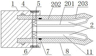
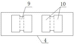
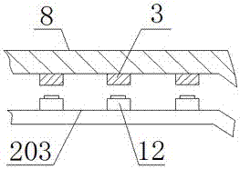
[0027] Such as Figure 1-3 As shown, a static contact for an isolating switch with a homing system includes a fixed head 1, a conductive splint 2 and a homing system arranged at the root of the conductive splint 2 and slidingly fitted with the conductive splint 2. The homing system includes a homing member 4 sleeved on the conductive splint 2, a spring 5, a limiting boss 7 on the conductive splint 2 for limiting the horizontal movement limit position of the homing member 4, and a fixedly arranged on the conductive splint 2 The outer guide sleeve 8, the root of the guide sleeve 8 is extended and connected in the fixed head 1 to consolidate the stability, such as figure 2 As shown, the returning member 4 is provided with a jack 9 for the conductive splint 2 to be inserted into, and the jack 9 respectively extends to both ends with a rail slot 10 for the conductive splint 2 to slide back and forth. The rail slot 10 The width is not less than the width of the socket 9, and a spring 5 is connected between the return piece 4 and the conductive splint 2. The setting of the return element is used to limit the action of the conductive splint, which ensures that the static contact is in use The action limit and automatic return after use, thereby avoiding deformation and excessive damage caused by changes in current and electromagnetic force; the end of the return piece 4 is set in the chute 6 inside the fixed head 1; The setting of the boss and the chute controls the horizontal and vertical movement of the homing member, which is more convenient for the homing control of the homing member to the conductive splint;
[0028] The conductive splint 2 is composed of two bent electromagnetic sheets 11. The conductive splint 2 includes an inner contact plate 201 in contact with the movable contact, an outer contact plate 202 in contact with the guide sleeve 8 and a connection between the inner contact plate 201 and the outer contact. The curved connecting portion 203 of the plate 202, and the outer side of the curved connecting portion 203 is arranged in contact with the guide sleeve 8, such as image 3 As shown, the outer side of the curved connecting portion 203 is fixedly provided with a telescopic sleeve 12, and the inner side of the guide sleeve 8 is fixedly provided with a boss 3 corresponding to the telescopic sleeve 12, which avoids the gap between the inner and outer sides of a single electromagnetic sheet. The electromagnetic repulsion force is too large to cause deformation of the electromagnetic sheet; the root of the conductive splint 2 is fixedly connected to the fixed head 1.
[0029] Further, the conductive clamping plate 2 is formed by two bent electromagnetic sheets 11 with the same shape arranged opposite to each other, which helps the movable contact to enter and be clamped.
[0030] Further, the width of the track slot 10 is greater than the width of the socket 9, which facilitates the insertion of the conductive splint and slides back and forth due to electromagnetic force, and can cooperate with the spring 5 to further limit the sliding position of the conductive splint, and limit its movement. .
[0031] Further, the root of the guide sleeve 8 is extended and connected in the fixed head 1 by bolts, which is safe, reliable, and stable.
[0032] Further, the guide sleeve 8 is a flat structure made of insulating material.
[0033] Further, the end of the return member 4 passes through the guide sleeve 8 and is set in the slide groove 6 inside the fixed head 1. The slide groove 6 limits the horizontal and vertical movement of the return member, which is convenient for the return member to conduct electricity. Home control of the splint.
[0034] When the repulsive force between the inner and outer sides of the same electromagnetic sheet and the attractive force between the inner contact plates of the two electromagnetic sheets clamp the movable contact at the same time, the greater the current, the greater the clamping force, which causes the dynamic contact The head is difficult to pull out and easy to damage due to excessive clamping force. On the other hand, the repulsive force between the inner and outer sides of the same electromagnetic sheet will cause deformation and damage to the electromagnetic sheet; The isolating switch of the system uses static contacts, and the homing system limits the action of the electromagnetic sheet, which ensures the action limit of the static contact during use and the automatic homing after use, thereby avoiding current and electromagnetic The deformation and excessive damage caused by the change of force are convenient for long-term use, convenient for maintenance, good performance, low cost, and have good application prospects.
[0035] The implementation of the present invention is not limited by the above-mentioned embodiments, and any other changes, modifications, substitutions, combinations, and simplifications made without departing from the spirit and principle of the present invention should be equivalent replacement methods, and are included in Within the protection scope of the present invention.

PUM

no PUM

Description & Claims & Application Information

We can also present the details of the Description, Claims and Application information to help users get a comprehensive understanding of the technical details of the patent, such as background art, summary of invention, brief description of drawings, description of embodiments, and other original content. On the other hand, users can also determine the specific scope of protection of the technology through the list of claims; as well as understand the changes in the life cycle of the technology with the presentation of the patent timeline. Login to view more.

Similar technology patents

Wood-plastic wallboard laying structure

Owner:ANHUI SENTAI WPC GRP CO LTD

Rotary power overhead transmission line deicing device

Owner:ZHENGZHOU TIANSHUN ELECTRONICS TECH CO LTD

Classification and recommendation of technical efficacy words

  • Simple structure
  • Innovative design

Sharing system for air-conditioning coat

InactiveCN107440179ASimple structureeasy to wear
Owner:QINGDAO HAIER AIR CONDITIONER GENERAL CORP LTD

Feeding device of sorter of batteries plate

InactiveCN101357717ASimple structurecooperate well
Owner:NANJING NORMAL UNIVERSITY

Emergency parachuting device and method for multiple-rotor unmanned aerial vehicle

InactiveCN103895870Aavoid aircraft crashSimple structure
Owner:SOUTH CHINA AGRI UNIV +1

Polishing device for dustless building grounds

Owner:CHANGSHA WUDAO IND DESIGN CO LTD
Why Eureka
Try Eureka