Clamping device

A clamping device and clamping element technology, which is applied in the field of workpiece clamping devices, can solve problems such as workpiece damage and the tool cannot reach the position of the workpiece, and achieve the effect of improving processing efficiency

Pending Publication Date: 2017-08-01
OMAX LTD
View PDF15 Cites 1 Cited by
  • Summary
  • Abstract
  • Description
  • Claims
  • Application Information

AI Technical Summary

Problems solved by technology

In addition, despite the use of clamping elements already known at the state of the art, the tool cannot reach the workpiece position due to the small height of the workpiece so that the two clamping elements are too close in the clamped state
At the same time, the already shaped window element is clamped in such a way that the window element protrudes upwards or downwards from the clamping element, as a result of which damage to the workpiece due to bending loads can occur during processing

Method used


Image

  • Clamping device
  • Clamping device
  • Clamping device

Examples


Embodiment Construction

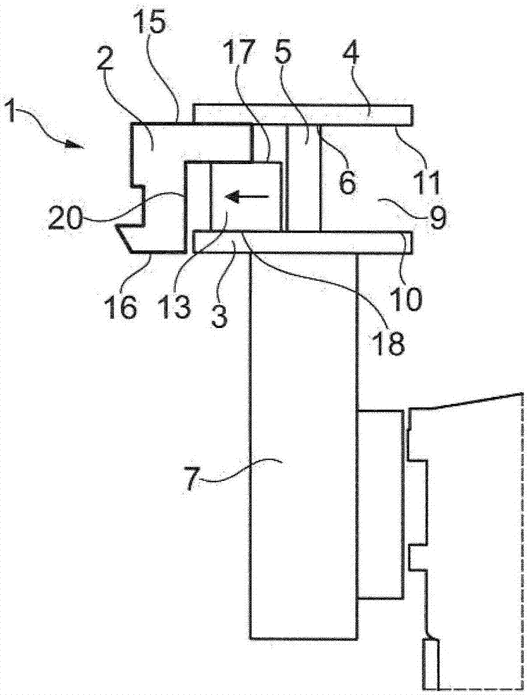
[0061] figure 1 A clamping device 1 is shown for clamping a workpiece 2 made of wood, plastic or similar material for processing it in a processing device.

[0062] The clamping device 1 has a lower clamping element 3 and an upper clamping element 4 . The upper clamping element 4 is adjustable in height relative to the height-immovable lower clamping element 3 . Optionally, the height of the lower element 3 can also be adjusted.

[0063] The upper clamping element 4 is flat or approximately flat, and is fixedly connected to the positioning rod 5 . Such as figure 1 As shown, the connection is made at the upper end 6 of the positioning rod 5 . Connections can also be made in other ways if necessary. A more favorable solution is that the connection between the upper clamping element 4 and the positioning rod 5 is a threaded connection. In addition, the positioning rod 5 and the upper clamping element 4 can also form an integral part.

[0064] Such as figure 1 As shown, the...


PUM


Abstract

The invention relates to a clamping device (1) for a workpiece (2), comprising a lower clamping element (3) and an upper clamping element (4) which form a workpiece holder (9). The height of the upper clamping element (4) can be adjusted relative to the lower clamping element (3), and the workpiece (2) has at least one outer surface (18) arranged on the lower face and can be inserted into the clamping device (1). The clamping device also comprises a clamping support element (13) which can be provided in the clamping device (1), said clamping support element (13) having at least one outer surface (17) arranged on the upper face. The workpiece (2) and the clamping support element (13) can be clamped together in the clamping device (1), wherein the at least one workpiece (2) outer surface (16) arranged on the lower face and the at least one clamping support element (13) outer surface (17) arranged on the upper face lie flat one on top of the other when the workpiece (2) and the clamping support element (13) are clamped in the clamping device (1).

Description

technical field [0001] The invention relates to a workpiece clamping device, in particular a clamping device for workpieces made of wood, plastic or similar material according to the preamble of claim 1 . Background technique [0002] When machining workpieces, such as window or door elements, especially when they are made of wood, plastic or similar materials, it is often necessary to mill a large number of different types of material in the workpiece. In addition, it is especially necessary to mill the longitudinal sides of the workpiece Perform extensive processing. [0003] In order to fulfill the recent growing desire to let more light into the living room, the width of individual window components is getting smaller and smaller. As a result, only a small free clamping surface of the workpiece is available for securing the workpiece in the clamping device during the cutting process. Typically, window elements of this type require several processing steps, in which one...

Claims


Application Information

Patent Timeline
Patent Type & Authority Applications(China)
IPC IPC(8): B23Q3/06B23Q3/00
CPCB23Q3/00B23Q3/06B25B5/061B25B5/067B25B5/163B27C5/06B25B5/087B25B5/062B25B5/003B25B5/142
Inventor 沃尔克·施密德克里斯蒂安·斯特姆斯特凡·弗里斯
Owner OMAX LTD
Why Eureka
Try Eureka