Polishing device for manufacturing of brake pads
A technology of brake pads and grinding mechanisms, which is applied in the direction of grinding/polishing safety devices, manufacturing tools, grinding machines, etc., and can solve the problems of inability to grind iron palms at the same time, low grinding efficiency, and a large amount of dust
- Summary
- Abstract
- Description
- Claims
- Application Information
AI Technical Summary
Problems solved by technology
Method used
Image

Examples
Embodiment 1
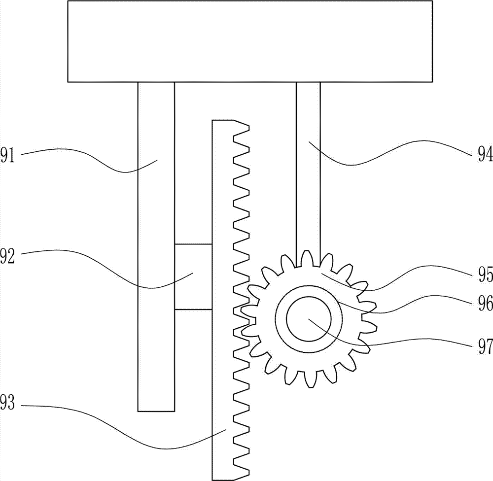
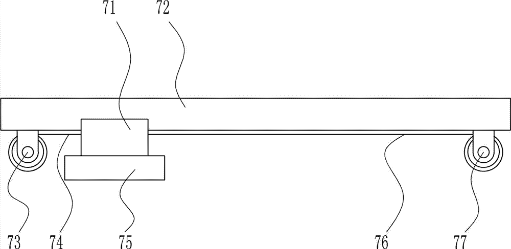
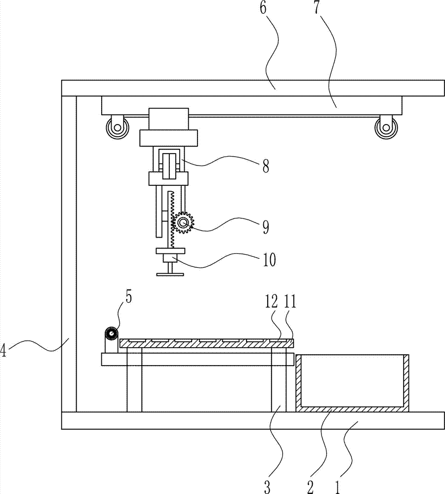
[0035] A grinding device for brake pad manufacture, such as Figure 1-6 As shown, it includes a bottom plate 1, a collection frame 2, a support seat 3, a left frame 4, a dust removal mechanism 5, a top plate 6, a left and right movement mechanism 7, a front and rear movement mechanism 8, a lifting mechanism 9, a grinding mechanism 10 and a placement plate 11, and the bottom plate 1. A collecting frame 2 is provided on the right side of the top. A support base 3 is installed in the middle of the top of the bottom plate 1. A placement plate 11 is connected to the support base 3. A placement slot 12 is opened on the placement plate 11. A dust removal mechanism 5 is connected to the support base 3. A left frame 4 is installed on the left side of the top of the bottom plate 1, a top plate 6 is connected to the top of the left frame 4, a left and right moving mechanism 7 is installed on the bottom of the top plate 6, a front and rear moving mechanism 8 is connected to the bottom of t...
Embodiment 2
[0037] A grinding device for brake pad manufacture, such as Figure 1-6 As shown, it includes a bottom plate 1, a collection frame 2, a support seat 3, a left frame 4, a dust removal mechanism 5, a top plate 6, a left and right movement mechanism 7, a front and rear movement mechanism 8, a lifting mechanism 9, a grinding mechanism 10 and a placement plate 11, and the bottom plate 1. A collecting frame 2 is provided on the right side of the top. A support base 3 is installed in the middle of the top of the bottom plate 1. A placement plate 11 is connected to the support base 3. A placement slot 12 is opened on the placement plate 11. A dust removal mechanism 5 is connected to the support base 3. A left frame 4 is installed on the left side of the top of the bottom plate 1, a top plate 6 is connected to the top of the left frame 4, a left and right moving mechanism 7 is installed on the bottom of the top plate 6, a front and rear moving mechanism 8 is connected to the bottom of t...
Embodiment 3
[0040] A grinding device for brake pad manufacture, such as Figure 1-6 As shown, it includes a bottom plate 1, a collection frame 2, a support seat 3, a left frame 4, a dust removal mechanism 5, a top plate 6, a left and right movement mechanism 7, a front and rear movement mechanism 8, a lifting mechanism 9, a grinding mechanism 10 and a placement plate 11, and the bottom plate 1. A collecting frame 2 is provided on the right side of the top. A support base 3 is installed in the middle of the top of the bottom plate 1. A placement plate 11 is connected to the support base 3. A placement slot 12 is opened on the placement plate 11. A dust removal mechanism 5 is connected to the support base 3. A left frame 4 is installed on the left side of the top of the bottom plate 1, a top plate 6 is connected to the top of the left frame 4, a left and right moving mechanism 7 is installed on the bottom of the top plate 6, a front and rear moving mechanism 8 is connected to the bottom of t...
PUM
| Property | Measurement | Unit |
|---|---|---|
| Height | aaaaa | aaaaa |
Abstract
Description
Claims
Application Information
 - Generate Ideas
- Intellectual Property
- Life Sciences
- Materials
- Tech Scout
- Unparalleled Data Quality
- Higher Quality Content
- 60% Fewer Hallucinations
Browse by: Latest US Patents, China's latest patents, Technical Efficacy Thesaurus, Application Domain, Technology Topic, Popular Technical Reports.
© 2025 PatSnap. All rights reserved.Legal|Privacy policy|Modern Slavery Act Transparency Statement|Sitemap|About US| Contact US: help@patsnap.com