Pin extractor

A technology of pins and outer casings is applied in the field of pin lifters, which can solve the problems of difficult cylindrical pin extraction, damage to parts and complicated operations, and achieve the effects of preventing falling off, being convenient to use and simple to operate.

Active Publication Date: 2017-08-04
卜钰
View PDF9 Cites 6 Cited by
  • Summary
  • Abstract
  • Description
  • Claims
  • Application Information

AI Technical Summary

Problems solved by technology

[0002] In the field of machinery, pins are widely used in various molds and equipment, and can play the role of positioning or connection. Cylindrical pins are commonly used pins, which are mostly installed on parts through interference fit. Cylindrical pins can be divided into It is a cylindrical pin with a threaded hole and a cylindrical pin without a threaded hole. The cylindrical pin with a threaded hole can be removed with a bolt suitable for the threaded hole. For the cylindrical pin without a threaded hole, due to the The installation hole of the pin is different, and its disassembly method is also different. On different parts, due to the design requirements, the installation hole of the cylindrical pin has two types: through hole and blind hole. For the through hole type installation hole, it can be used The punch punches out the cylindrical pin from one end of the through hole, and for the blind hole type mounting hole, since the exposed part of the cylindrical pin outside the component is very short, generally not more than 5mm, it is difficult to use tools such as pliers. Pulling out the cylindrical pin. At present, in order to solve the problem of pulling out the cylindrical pin in the blind hole, a bolt is often welded on the exposed part of the cylindrical pin, and the cylindrical pin is pulled out by pulling the bolt. The operation is extremely complicated and the efficiency is low. And during the welding process, it will cause certain damage to the parts where the cylindrical pin is installed

Method used


Image

  • Pin extractor
  • Pin extractor
  • Pin extractor

Examples


Embodiment

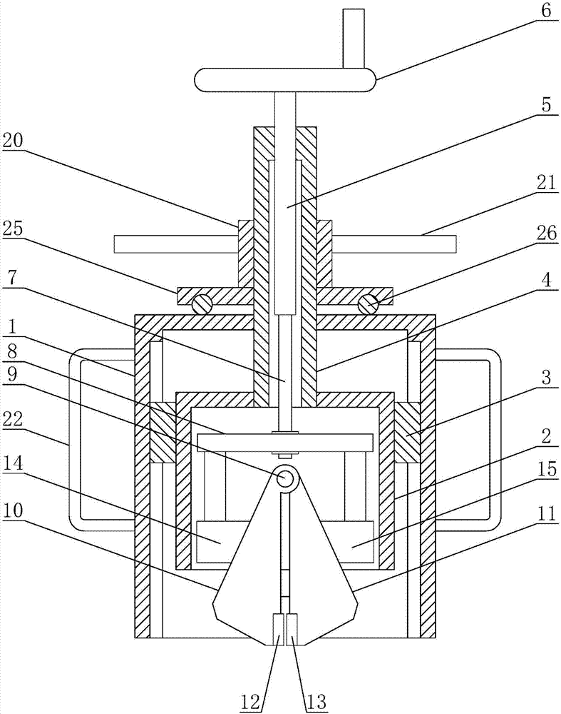
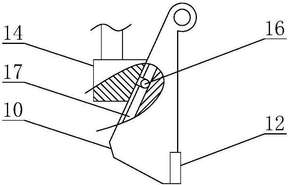
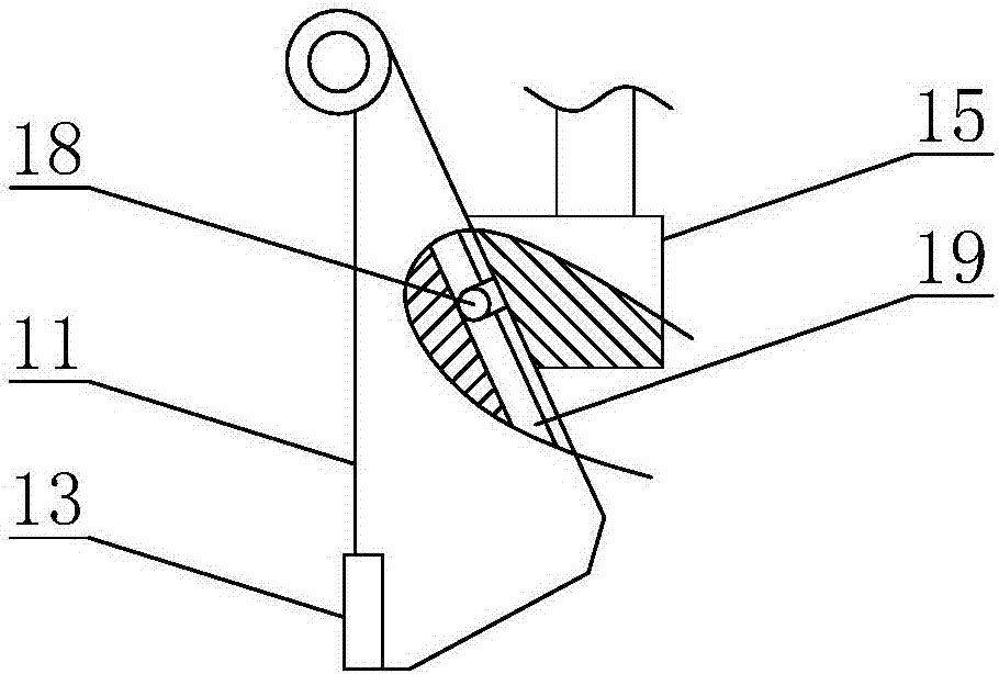
[0028] Embodiment: The present invention is a pin extractor, which includes an outer shell 1, and a handle 22 is welded on the outer wall of the outer shell 1, which can facilitate the carrying of the present invention and the use of the present invention. The outer shell 1 is provided with an inner shell 2, the outer wall of the inner shell 2 is provided with two sliders 3, and the inner wall of the outer shell 1 is provided with a chute adapted to the slider 3, The inner casing 2 is slidingly connected with the outer casing 1 . One end of the outer casing 1 is provided with an opening compatible with the inner casing 2, and the inner casing 2 can extend out of the outer casing 1 through the opening. The end of the inner casing 2 away from the opening is welded with a support cylinder 4 , and the support cylinder 4 communicates with the inner casing 2 . The end of the outer shell 1 away from the opening is provided with a through hole adapted to the support cylinder 4, and t...


PUM


Abstract

The invention discloses a pin extractor, and mainly relates to the technical field of machinery. The pin extractor comprises an outer shell, wherein an inner shell is arranged inside the outer shell; an opening corresponding to the inner shell is formed in one end of the outer shell; a supporting barrel is arranged at one end, which is far away from the opening, of the inner shell; a through hole matched with the supporting hole is formed in one end, which is far away from the opening, of the outer shell; a screw rod is arranged in the supporting barrel; a handwheel is arranged at one end of the screw rod, and a supporting rod is arranged at the other end of the screw rod; a supporting block is arranged on the supporting rod; a hinge shaft is arranged on one side, which is far away from the supporting rod, of the supporting block; a first wedge-shaped chuck and a second wedge-shaped chuck are arranged on the hinge shaft; a thread sleeve is arranged on the supporting barrel in a sleeving manner; and a rotating arm is arranged on the outer wall of the thread sleeve. The pin extractor has the beneficial effect that removal of a pin from a blind hole can be quickly completed; the pin extractor is easy to operate and convenient to use; the working efficiency can be improved; and damage to a straight pin and a part for installing the straight pin can be avoided.

Description

technical field [0001] The invention relates to the technical field of machinery, in particular to a pin ejector. Background technique [0002] In the field of machinery, pins are widely used in various molds and equipment, and can play the role of positioning or connection. Cylindrical pins are commonly used pins, which are mostly installed on parts through interference fit. Cylindrical pins can be divided into It is a cylindrical pin with a threaded hole and a cylindrical pin without a threaded hole. The cylindrical pin with a threaded hole can be removed with a bolt suitable for the threaded hole. For the cylindrical pin without a threaded hole, due to the The installation hole of the pin is different, and its disassembly method is also different. On different parts, due to the design requirements, the installation hole of the cylindrical pin has two types: through hole and blind hole. For the through hole type installation hole, it can be used The punch punches out the ...

Claims


Application Information

Patent Timeline
Patent Type & Authority Applications(China)
IPC IPC(8): B25B27/02
CPCB25B27/023
Inventor 卜钰
Owner 卜钰
Why Eureka
Try Eureka