
Digital polymerase chain reaction detection chip, method and liquid path system thereof

A chain reaction and detection chip technology, applied in chemical instruments and methods, biochemical equipment and methods, bioreactor/fermenter combinations, etc., can solve the problems of sample droplet contamination, difficult cleaning, dead volume, etc. Reasonable pipeline design, reducing pollution and small dead volume

Active Publication Date: 2017-08-04
广东永诺医疗科技有限公司
View PDF6 Cites 3 Cited by
  • Summary
  • Abstract
  • Description
  • Claims
  • Application Information

AI Technical Summary

Problems solved by technology

However, the pipeline design of the liquid system in the traditional digital polymerase chain reaction detection chip is unreasonable, and the loss and dead volume of the sample droplets in the pipeline are relatively serious. The loss in the sample will be more serious, which will lead to low utilization rate and large loss of sample droplets, and the amount of sample that can be analyzed and detected is small.
[0004] In addition, after the digital polymerase chain reaction detection chip detects and analyzes the sample droplets, in order to avoid pollution to the subsequent detection, it is necessary to clean the pipeline through which the sample droplets flow. The liquid in the traditional digital polymerase chain reaction detection chip There will be dead volume in the sampling pipeline of the system, which is difficult to clean and may easily cause contamination between the sample droplets

Method used


Image

  • Digital polymerase chain reaction detection chip, method and liquid path system thereof
  • Digital polymerase chain reaction detection chip, method and liquid path system thereof
  • Digital polymerase chain reaction detection chip, method and liquid path system thereof

Examples


Embodiment Construction

[0035] In order to facilitate the understanding of the present invention, the present invention will be described more fully below with reference to the associated drawings. Preferred embodiments of the invention are shown in the accompanying drawings. However, the present invention can be embodied in many different forms and is not limited to the embodiments described herein. On the contrary, these embodiments are provided to make the understanding of the disclosure of the present invention more thorough and comprehensive.

[0036] It should be noted that when an element is referred to as being “fixed” to another element, it can be directly on the other element or there can also be an intervening element. When an element is referred to as being "connected to" another element, it can be directly connected to the other element or intervening elements may also be present.

[0037]Unless otherwise defined, all technical and scientific terms used herein have the same meaning as ...


PUM


Abstract

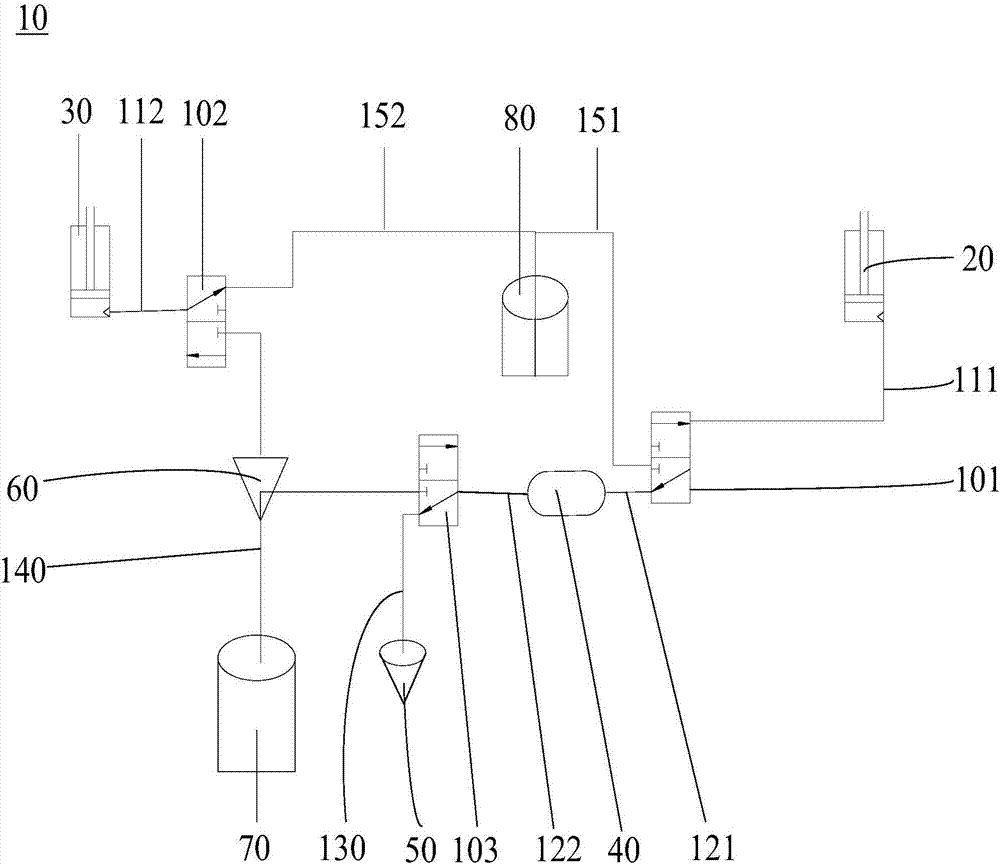
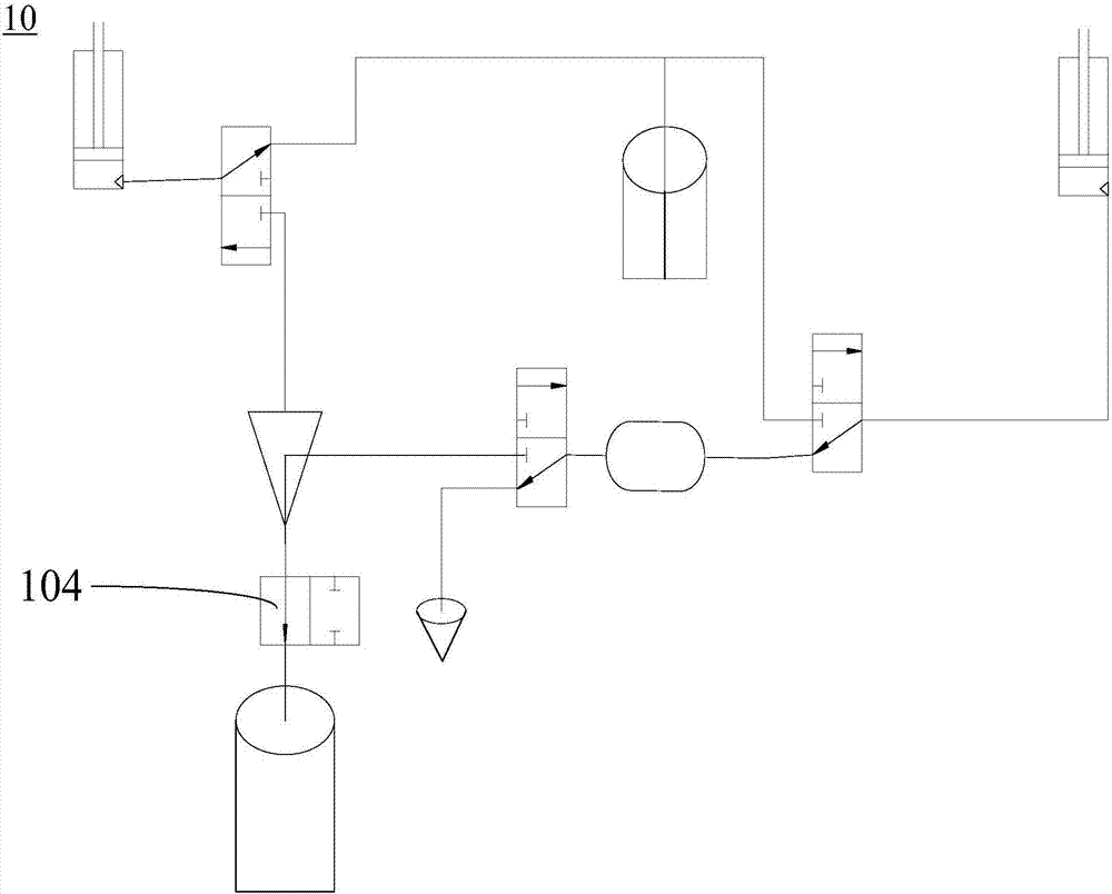
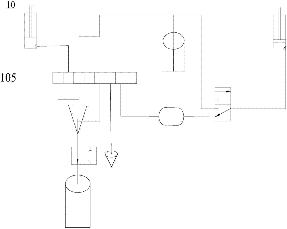
The invention relates to a digital polymerase chain reaction detection chip, a method and a liquid path system thereof. The liquid path system of the digital polymerase chain reaction detection chip comprises a first communicating valve, a second communicating valve, a third communicating valve, a first suction and injection pipeline, a second suction and injection pipeline, a first liquid storage pipeline, a second liquids storage pipeline, a sample inlet pipeline, a detection pipeline, a first oil delivery pipeline and a second oil delivery pipeline. One end of the first suction and injection pipeline is connected to the first suction and injection device while the other end is connected to the first communicating valve; one end of the second suction and injection pipeline is connected to the second suction and injection pipeline while the other end is connected to the second communicating valve; one end of the first liquid storage pipeline is connected to the first communicating valve while the other end of the first liquid storage pipeline is connected to a liquid storage device, one end of the second liquid storage pipeline is connected to the liquid storage device while the other end of the second liquid storage pipeline is connected to the third communicating valve. The pipelines of the polymerase chain reaction detection chip in the liquid path system are simple in structure and easy to clean.

Description

technical field [0001] The invention relates to the technical field of polymerase chain reaction detection, in particular to a digital polymerase chain reaction detection chip, a method and a liquid path system thereof. Background technique [0002] Polymerase Chain Reaction (PCR) is a molecular biology technique for amplifying specific nucleic acids in vitro, which has the advantages of strong specificity, high sensitivity, high efficiency and quick operation, and simple operation. Among them, Digital Polymerase Chain Reaction (Digital Polymerase Chain Reaction, dPCR) is the third generation of PCR technology. Digital Polymerase Chain Reaction divides the PCR reaction system containing primers, templates, fluorescent probes, polymerase and other components into Numerous tiny, independent reaction units. After the PCR amplification reaction, the fluorescence signal of each reaction unit is detected, and the droplets with target DNA fragments will emit strong fluorescence af...

Claims


Application Information

Patent Timeline
Patent Type & Authority Applications(China)
IPC IPC(8): C12M1/34C12M1/00B01L3/00C12Q1/68
CPCB01L3/502784B01L3/54B01L2200/141B01L2400/0622C12Q1/686C12Q2563/159C12Q2563/107
Inventor 陈庆明李冬梅关国坚林超
Owner 广东永诺医疗科技有限公司
Learn More