
Eureka
For R&D, Eureka makes reading and utilizing patents & technical documents easy.
Eureka AIR
Designed for self-driven R&D workflows. Generate viable solutions, solve complex R&D challenges, empower your innovation with AI.

Eureka Materials
Designed for material experts only. Revolutionize your material R&D, from search, analyze, to developing new materials.

TechResearch
Generate reliable direction feasibility study reports for your R&D in just a few steps.

TechSeek
Discover and master advanced knowledge NOW. Basics, ideas, possibilities, all at once.

TechMind
As an expert in R&D Theories, TechMind can generates customized viable solutions instantly.

TechRisk
Analyze your overall solution with one click, know your potential R&D risks in advance.

TechMonitor
Get weekly tech updates, stay abreast of the latest tech innovations and key insights.
Plastic pipeline fire retardant ring
A technology of plastic pipes and fire arresting rings, which is applied in the direction of pipes, pipes/pipe joints/fittings, mechanical equipment, etc., can solve the problems of easy falling off of parts, inconvenient, lost installation, etc., to save manpower and cost, save installation time-saving effect
- Summary
- Abstract
- Description
- Claims
- Application Information
AI Technical Summary
Problems solved by technology
Method used
Image

Examples
Embodiment 1
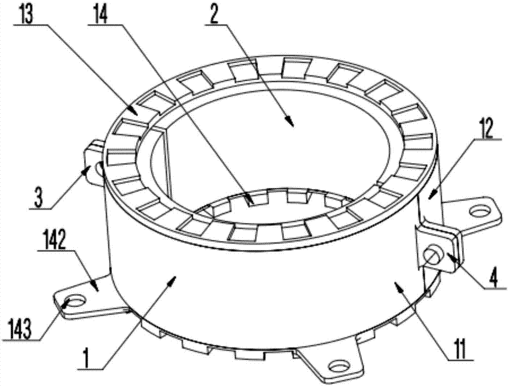
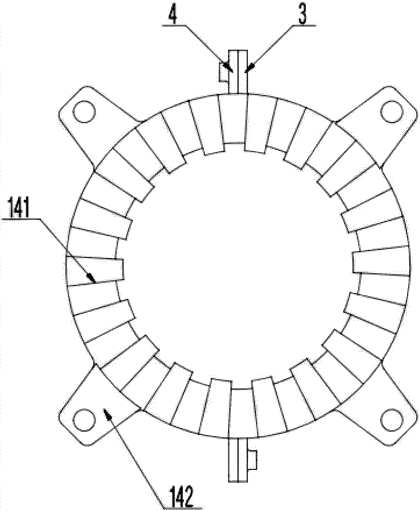
[0036] figure 1 It is a three-dimensional structural schematic diagram of the plastic pipe fire stop ring provided by the embodiment of the present invention; figure 2 is the bottom view of the plastic pipe flame arrester provided by the embodiment of the present invention; such as figure 1 and 2 As shown, this embodiment provides a plastic pipe fire stop ring, including an outer shell 1 and an annular inner core 2; the annular inner core 2 is made of a flame-retardant expansion core material, which is used for thermal expansion and blocking the pipe penetration to prevent The fire spread along the mouth of the cave.
[0037] Preferably, the flame-retardant expanded core material is an annular graphite ribbon.
[0038] Plastic pipes are widely used in all kinds of public and civil buildings, but plastic pipes are often easy to become a channel for fire propagation. The holes formed by plastic pipes after being burned by heat are like a chimney, which makes flames and smoke...
Embodiment 2
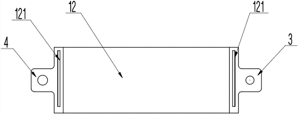
[0045] image 3 Yes figure 1 Front view of the second side housing shown; Figure 4 Yes image 3 a top view of the second side housing shown; Figure 5 Yes figure 1 Front view of the first side housing shown; Image 6 Yes Figure 5 Sectional view at A-A of the first side housing shown; as Figure 3-6 As shown, on the basis of the above-mentioned embodiment, this embodiment further improves the plastic pipe flame arrester. It is integrally formed with the second ear plate 4 .
[0046] Preferably, both the first ear plate 3 and the second ear plate 4 are arranged at the ends of the first side shell 11 and the second side shell 12 .
[0047]Preferably, both the first ear plate 3 and the second ear plate 4 are arranged in the middle position of the junction of the first side shell 11 and the second side shell 12 .
[0048] Preferably, both the first ear plate 3 and the second ear plate 4 are configured as rectangular flat plates.
[0049] Preferably, the connecting surfa...
Embodiment 3
[0054] Figure 7 Yes figure 1 front view of the housing shown; Figure 8 Yes Figure 7 Sectional view shown at housing B-B; as Figure 7 and 8 As shown, on the basis of the above-mentioned embodiment, this embodiment further improves the plastic pipe flame arrester. Specifically, the first side shell 11 is provided with a tongue groove 111, A tongue 121 is provided to be inserted into the tongue groove 111; the tongue groove 111 and the tongue 121 (eg Figure 4 shown) to form an interference fit.
[0055] Preferably, the tongue groove 111 is provided with a convex portion, and the tongue 121 is provided with a concave portion matched with the boss.
[0056] The plastic pipe flame arrester provided by the present invention can strengthen the connection strength between the first side shell 11 and the second side shell 12 .
PUM
 Abstract
Description
Claims
Application Information
 - R&D Engineer
- R&D Manager
- IP Professional
- Industry Leading Data Capabilities
- Powerful AI technology
- Patent DNA Extraction
Browse by: Latest US Patents, China's latest patents, Technical Efficacy Thesaurus, Application Domain, Technology Topic, Popular Technical Reports.
© 2024 PatSnap. All rights reserved.Legal|Privacy policy|Modern Slavery Act Transparency Statement|Sitemap|About US| Contact US: help@patsnap.com