Control method for chilled water valve

A control method and chilled water technology, applied in heating and ventilation control systems, heating methods, lighting and heating equipment, etc., can solve problems such as low adjustment accuracy and slow adjustment speed of chilled water valves, and achieve high-precision control effects

Inactive Publication Date: 2017-08-04
GREE ELECTRIC APPLIANCES INC
View PDF7 Cites 8 Cited by
  • Summary
  • Abstract
  • Description
  • Claims
  • Application Information

AI Technical Summary

Problems solved by technology

[0005] In the embodiment of the present invention, a control method of the chilled water valve is provided to so

Method used


Image

  • Control method for chilled water valve
  • Control method for chilled water valve
  • Control method for chilled water valve

Examples


Embodiment Construction

[0033] The present invention will be described in further detail below in conjunction with the accompanying drawings and specific embodiments, but not as a limitation of the present invention.

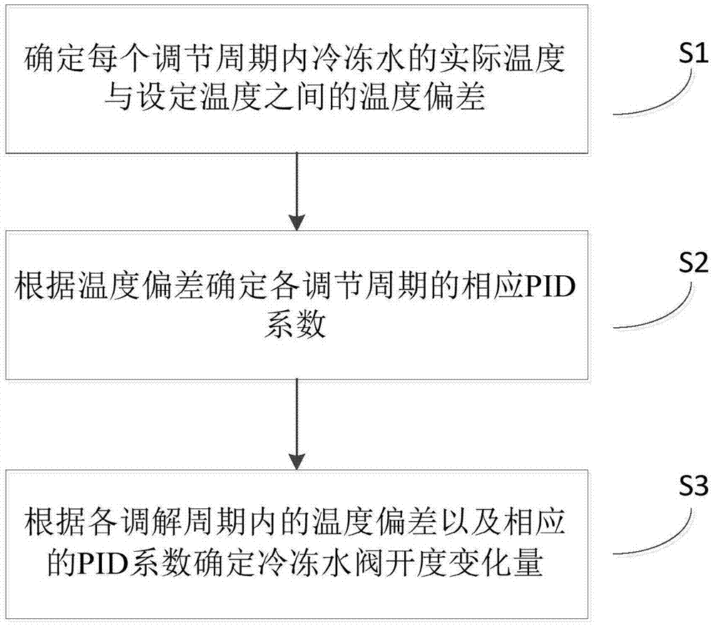
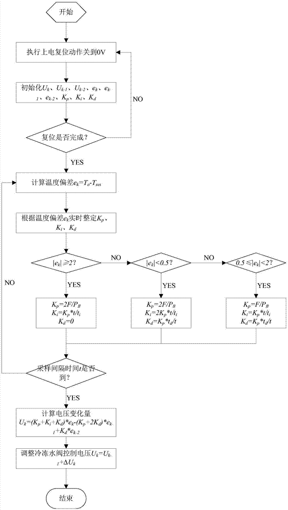
[0034] see in conjunction Figure 1 to Figure 3 As shown, according to the embodiment of the present invention, the control method of the chilled water valve includes: Step S1: Determine the temperature deviation between the actual temperature of the chilled water and the set temperature in each adjustment cycle; Step S2: Determine each temperature deviation according to the temperature deviation The corresponding PID coefficients of the adjustment period; Step S3: Determine the amount of change in the opening of the chilled water valve according to the temperature deviation in each adjustment period and the corresponding PID coefficients.

[0035] In the process of controlling the chilled water valve, the corresponding PID coefficient can be determined according to the temperature dev...


PUM


Abstract

The invention discloses a control method for a chilled water valve. The control method for the chilled water valve comprises the following steps: step S1, determining the temperature deviation between an actual temperature and a set temperature of chilled water in every regulation period; step S2, determining the corresponding PID coefficient of every regulation period according to the temperature deviation; and step S3, determining the changes of the opening degree of the chilled water valve according to the temperature deviation and the corresponding PID coefficient in every regulation period. The control method for the chilled water valve, disclosed by the invention, can solve the problems that the chilled water valve in the prior art is low in regulation speed and low in regulation precision.

Description

technical field [0001] The invention relates to the technical field of air conditioning control, in particular to a method for controlling a chilled water valve. Background technique [0002] The traditional chilled water flow adjustment is relatively simple, some use fixed frequency pumps or various valves to open and close according to the temperature difference, some use adjustable valve body or variable frequency pump with adjustable speed to control the chilled water flow control. [0003] The patent No. 201420285296.1 discloses a variable pressure difference control device based on the opening of the chilled water valve of the terminal air conditioner, and adjusts the operating speed of the variable frequency water pump through the collection parameters of various pressure sensors, temperature sensors, and flow sensors. Although this solution is stable and safe in control, it needs to use various sensors, frequency converters, etc., and the cost is relatively high, wh...

Claims


Application Information

Patent Timeline
IPC IPC(8): F24F11/00
CPCF24F11/64F24F11/83F24F11/84
Inventor 郭玉华韩定陈晓江石静波缪玉珍
Owner GREE ELECTRIC APPLIANCES INC
Why Eureka
Try Eureka