Luminous potentiometer

A potentiometer and brush technology, applied in the field of electronics, can solve the problems of inconvenient use, damage to the friction resistance body and high cost, and achieve the effect of maintaining the accuracy of positioning, maintaining stability and good performance.

Inactive Publication Date: 2017-08-04
成都灯岛科技有限公司
View PDF6 Cites 0 Cited by
  • Summary
  • Abstract
  • Description
  • Claims
  • Application Information

AI Technical Summary

Problems solved by technology

Multiple adjustments will cause friction between the contact and the resistor body and cause damage to the resistor body. At the same time, the subsequent adjustment is not accurate enough, and there is a technical problem that it is difficult to locate during the adjustment process.
[0004] At present, in order to reduce the cost, the push handle is made of plastic material, which has poor wear resistance. If it is made of metal material, the cost is too high
Existing push handles often do not have luminous function, which is inconvenient to use in a dark environment

Method used


Image

  • Luminous potentiometer
  • Luminous potentiometer
  • Luminous potentiometer

Examples


Embodiment Construction

[0016] The present invention will be further described below in conjunction with accompanying drawing and specific embodiment:

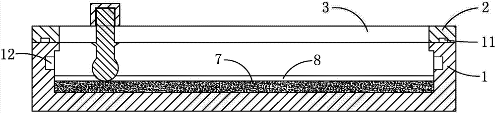
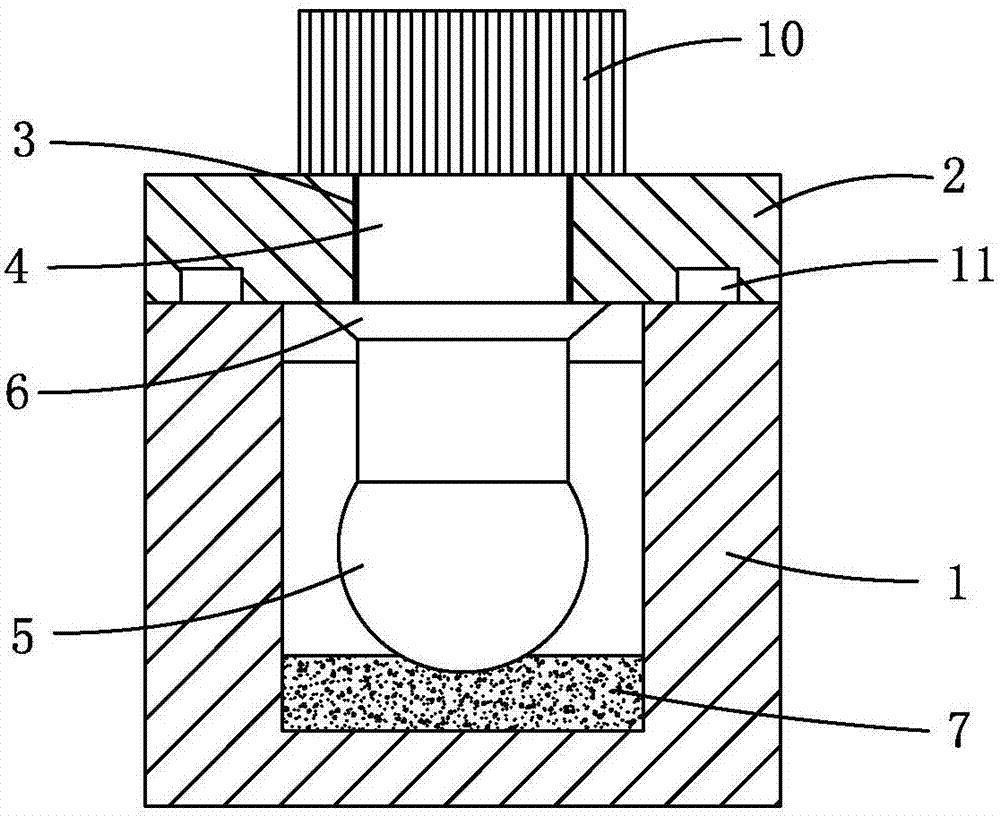
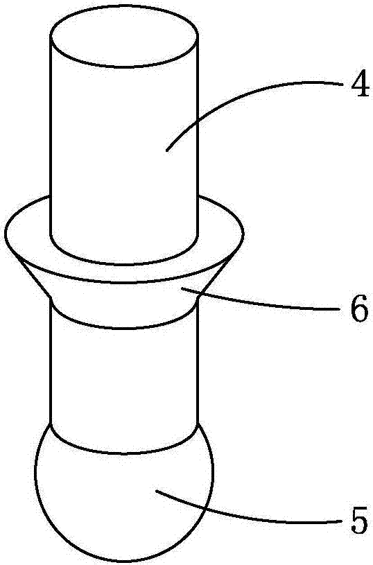
[0017] Such as Figure 1 to Figure 5 As shown, a luminous potentiometer of the present invention includes a housing 1 and a cover plate 2. The housing 1 is in the shape of a cuboid, and its top opening forms a cavity. The bottom of the cavity is laid with a resistor 7, and the cover plate 2 is sealed. On the housing 1 , a rectangular chute 3 is provided on the cover 2 , and the chute 3 is opposite to the top opening of the housing 1 . There is a cylindrical push handle 4 in the chute 3, and the push handle 4 can move along the length direction of the chute 3; the lower end of the push handle 4 is connected with the spherical brush part 5, and the resistor body 7 is provided with 5 matching arc-shaped groove 8, the brush part 5 is connected with the arc-shaped groove 8 in sliding contact. The resistance body 7 will be worn during use, but the arc-sh...


PUM


Abstract

The invention discloses a luminous potentiometer, which comprises a shell with an open top and a cover plate covering the shell, a chute is arranged on the cover plate, and a push handle is arranged in the chute; The brush part is connected, and a resistor body is provided inside the shell, and an arc-shaped groove matching the brush part is arranged on the resistor body, and the brush part is connected with the arc-shaped groove by sliding contact; the upper end of the push handle is threadedly connected with the push cap, and the push The cap includes a metal cap provided with an internal thread, and the outer surface of the metal cap is provided with a plastic cap; the outer surface of the metal cap has a luminous coating, and the plastic cap is made of transparent plastic. In the luminous potentiometer of the present invention, when the resistor body wears out, the arc-shaped groove always limits the position of the brush part, so as to maintain the stability and positioning accuracy when the push handle is pushed. The push cap adopts the matching structure of metal cap and plastic cap, which has good performance. The luminous coating inside the push cap has a luminous function, which is convenient for people to use at night.

Description

technical field [0001] The invention belongs to the field of electronic technology, and in particular relates to a luminous potentiometer. Background technique [0002] A potentiometer is an adjustable electronic component consisting of a resistive body and a turning or sliding system. When a voltage is applied between the two fixed contacts of the resistor body, the position of the contact on the resistor body is changed by rotating or sliding the system, and a position corresponding to the position of the movable contact can be obtained between the movable contact and the fixed contact. into a certain relationship with the voltage. Potentiometers are often used as voltage dividers, rheostats, and current controllers, and are widely used in industries such as measuring instruments, fax machines, copiers, printers, and sensors. [0003] Potentiometers with a sliding system generally change the position of the contacts on the resistor body by pushing the push handle. Multi...

Claims


Application Information

Patent Timeline
Patent Type & Authority Applications(China)
IPC IPC(8): H01C10/38H01C1/04H01C1/16
CPCH01C10/38H01C1/04H01C1/16
Inventor 李豪
Owner 成都灯岛科技有限公司
Why Eureka
Try Eureka