Rapid cutover method based on circuit configuration pair

A circuit configuration and circuit technology, applied in the direction of electrical components, digital transmission systems, transmission systems, etc., can solve the problems of long execution time, high risk, and high complexity of transmission network, so as to improve the use time, reduce the time, and reduce the risk. Effect

Inactive Publication Date: 2017-08-04
FENGHUO COMM SCI & TECH CO LTD
4 Cites 4 Cited by

AI-Extracted Technical Summary

Problems solved by technology

[0003] The technical problem to be solved by the present invention is that due to the increasing complexity of the transmission network, the circuit cutover operation due to net...

Method used

The present invention can configure the cutover task and the cutover pair on the network management offline before the cutover, forming a circuit configuration pair before and after the cutover, thereby generating incremental network element configuration data before and after the cutover, before the cutover is performed Download the configuration data of the incremental network element generated by the circuit configuration pair to the physical network element. In this process, the original circuit will not be interrupted, thereby increasing the use time of the ...

Abstract

The invention discloses a rapid cutover method based on a circuit configuration pair. The method comprising the steps of building a cutover task, building cutover pairs in the cutover task, assigning a circuit before cutover for each cutover pair, and building a corresponding circuit after cutover; forming network elements of the cutover pairs into the circuit configuration pair one by one, and setting the attribute of the circuit configuration pair, wherein the circuit configuration pair comprises configuration before cutover and configuration after cutover corresponding to the circuits before and after cutover; configuring each network element in the circuit configuration pair to a network element configuration library, performing incremental isolation on the configuration before cutover and the new configuration after cutover according to the configuration attribute in the circuit configuration pair by using the network element; executing a cutover task, and starting the circuit configuration pair so as to make the configuration before cutover be invalid, and bring the configuration after cutover into effect; after the cutover is successful, deleting the configuration before cutover in the circuit configuration pair. According to the method provided by the invention, service life of the original circuit is improved, switching time of the circuit is reduced, and uninterrupted cutover of the circuit is achieved, and a cutover risk is reduced,

Application Domain

Data switching networks

Technology Topic

Network elementComputer engineering +2

Image

  • Rapid cutover method based on circuit configuration pair
  • Rapid cutover method based on circuit configuration pair
  • Rapid cutover method based on circuit configuration pair

Examples

  • Experimental program(1)

Example Embodiment

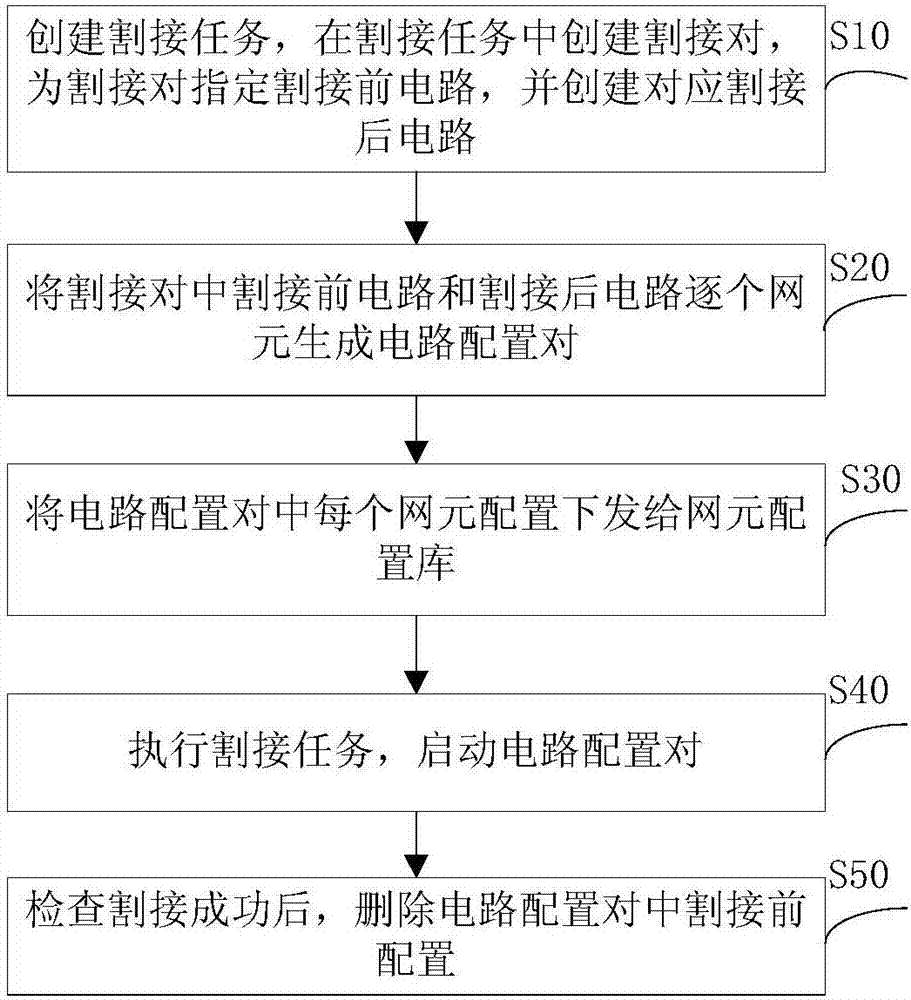
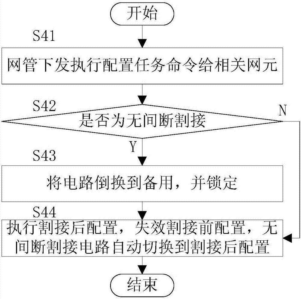
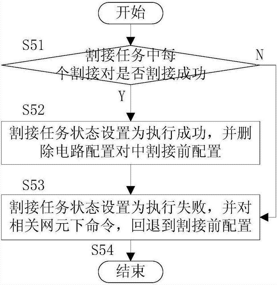
[0037] The present invention can configure cutover tasks and cutover pairs offline on the network management before cutover to form circuit configuration pairs before and after cutover, thereby generating incremental network element configuration data before and after cutover, and configure the circuit before the cutover is executed. Downloading the configuration data of the incremental network element to the physical network element will not cause the interruption of the original circuit in this process, thereby increasing the use time of the original circuit and greatly reducing the interruption time of circuit switching , And when performing cutover tasks, for the circuits whose source and sink do not change, switch to the protection circuit first, and then perform the cutover configuration to replace, so as to achieve circuit cutover without interruption. In addition, in the case of unsuccessful cutover, since the configuration generated by the circuit configuration pair before the cutover is retained on the network element device, the rollback can be quickly realized, which greatly reduces the risk of cutover.
[0038] The present invention will be described in detail below with reference to the drawings and specific embodiments of the specification.
[0039] Such as figure 1 As shown, a fast cutover method based on circuit configuration pairs provided by the present invention includes the following steps:
[0040] Step S10: Create a cutover task, create a cutover pair in the cutover task, and specify a pre-cutover circuit for each cutover pair, and create a corresponding post-cutover circuit.
[0041] In the present invention, step S10 specifically includes the following steps:
[0042] Step S11. Create a cutover task and set the task attributes. The task attributes of the cutover task include task name, user, planned execution time, actual execution time, task status, etc., among which the task status includes pending execution, successful execution, failed execution Three types; specific task attributes are shown in Table 1.
[0043] Table 1 Task attribute table of cutover task.
[0044]
[0045]
[0046] Step S12. Create a cutover pair in the cutover task, and determine whether it is a seamless cutover, if so, go to step S13; if it is not a seamless cutover, you do not need to switch to the protection circuit, because these circuits are in the configuration switching process There will inevitably be instantaneous interruption, and it is impossible to completely interrupt without interruption; execute step S14;
[0047] Uninterrupted cutover refers to the situation where the source and sink of the circuit do not change, and the protection circuit is switched to during the cutover process to ensure that the circuit is not interrupted during the cutover process. In the present invention, multiple cutover pairs can be created in one cutover task, and each cutover pair has a unique identification ID.
[0048] Step S13: Switch to the protection circuit first, so that the circuit between the source and the sink is not interrupted during the cutover process;
[0049] Step S14. Specify a pre-cutover circuit for each cutover pair and create a corresponding post-cutover circuit; among them, the pre-cutover circuit of a cutover pair can have one or more circuits, and the post-cutover circuit of a cutover pair There is only one.
[0050] Step S20: Generate a circuit configuration pair including a pre-cutover configuration and a post-cutover configuration from the pre-cutover circuit and the post-cutover circuit in the cutover pair, and set the attributes of the circuit configuration pair.
[0051] In the present invention, the attributes of the circuit configuration pair include cutover pair ID, network element ID, configuration category, configuration data block, etc. in each network element. The cutover pair ID uniquely identifies a cutover pair, and the network element ID is unique Identifies a physical network element. The configuration types include pre-cutover and post-cutover. The configuration data block includes the incremental network element configuration data set generated by the cutover pair before or after the cutover, specifically each network element The attributes of the above circuit configuration pair are shown in Table 2:
[0052] Table 2: Attribute table of circuit configuration pairs on network elements.
[0053]
[0054]
[0055] Step S30. The configuration of each network element in the circuit configuration pair is issued to the network element configuration library, and the network element incrementally isolates the pre-cutover configuration and the newly configured post-cutover configuration according to the configuration category attributes of the circuit configuration pair. The circuit configuration is placed on the physical network element corresponding to the data delivery, and incremental configuration isolation is performed according to the cutover pair ID and configuration category.
[0056] Step S40, execute the cutover task, start the circuit configuration pair, make the configuration before cutover invalid, and the configuration after cutover take effect.
[0057] Such as figure 2 As shown, step S40 includes the following steps:
[0058] Step S41: The network manager issues a command to execute configuration tasks to relevant network elements;
[0059] Step S42, judge whether it is a seamless cutover, if it is a seamless cutover, go to step S43; otherwise, go to step S44;
[0060] Step S43: Switch the circuit to standby and lock it;
[0061] Step S44: Perform post-cutover configuration, fail the pre-cutover configuration, and the seamless cutover circuit automatically switches to the post-cutover configuration, that is, the protection circuit of the circuit before cutover is switched to the working circuit of the circuit after cutover.
[0062] Step S50: After the cutover is successful, delete the circuit configuration alignment before the cutover configuration, such as image 3 As shown, it specifically includes the following steps:
[0063] Step S51, check whether each cutover pair in the cutover task is cutover successfully, if all the cutover pairs are successful, go to step S52; otherwise, go to step S53;
[0064] Step S52: Set the status of the cutover task to execute successfully, and delete the circuit configuration centering configuration before cutover, and then go to step S54;
[0065] Step S53: Set the status of the cutover task to execution failure, and issue a command to the relevant network element to roll back to the pre-cutover configuration;
[0066] Step S54: End the program.
[0067] Obviously, those skilled in the art can make various changes and modifications to the present invention without departing from the spirit and scope of the present invention. In this way, if these modifications and variations of the present invention fall within the scope of the claims of the present invention and their equivalent technologies, the present invention is also intended to include these modifications and variations.

PUM

no PUM

Description & Claims & Application Information

We can also present the details of the Description, Claims and Application information to help users get a comprehensive understanding of the technical details of the patent, such as background art, summary of invention, brief description of drawings, description of embodiments, and other original content. On the other hand, users can also determine the specific scope of protection of the technology through the list of claims; as well as understand the changes in the life cycle of the technology with the presentation of the patent timeline. Login to view more.

Similar technology patents

Method for detecting related substances in imidafenacin

Owner:NANJING HEALTHNICE MEDICAL TECH +1

Hydraulic linkage hydraulic counterblow hammer

ActiveCN103769511AReduce maintenance timesextended use time
Owner:JIANGSU BAIXIE PRECISION FORGING MACHINERY

Flushing device

InactiveCN101676497Aextended use time
Owner:DELTA ELECTRONICS INC

Easily-degradable synthetic resin tile and preparation method thereof

InactiveCN110271253ANot easy to fadeextended use time
Owner:福建祥龙塑胶有限公司

Classification and recommendation of technical efficacy words

  • extended use time
  • shorten the time
Why Eureka
Try Eureka