Straight type anchor wing rod

A bolt and straight plate technology, which is applied in the installation of bolts, mining equipment, earthwork drilling and mining, etc., can solve problems such as the expansion of the end of the bolt, and achieve good support effects, significant engineering benefits, and convenient use

Inactive Publication Date: 2017-08-08
SUZHOU SPARKS PRECISION MACHINERY CO LTD
View PDF0 Cites 2 Cited by
  • Summary
  • Abstract
  • Description
  • Claims
  • Application Information

AI Technical Summary

Problems solved by technology

[0003] In order to solve the problem that the existing construction method cannot solve the problem of the expansion of the end of the anchor rod, the present invention provides a straight plate type anchor rod wing, which can achieve the expansion of the end of the anchor section while adapting to the general construction method. purpose, the support effect is good, and the project benefit is remarkable

Method used


Image

  • Straight type anchor wing rod

Examples


Embodiment Construction

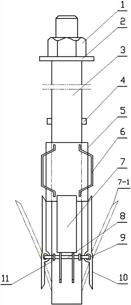
[0011] exist figure 1 Among them, the straight plate type anchor rod, including: anchor nut 1, washer plate 2, anchor rod body 3, stop pin 4, push wing steel pipe 5, positioning rib 6, wing 7, opened wing 7- 1. Reinforcement ring 8, wing ring 9, support column 10, fixed ring 11; the straight plate anchor wing has a cylindrical anchor body 3, and the lower part of the anchor body 3 is covered with a steel ring 8. A fixed fixed ring 11 is evenly arranged on the steel ring 8 and is connected to the wing 7 with the rotatable wing ring 9; the wing 7 is supported in parallel and stands on one side of the anchor rod body 3; The bottom of the wing 7 is a support station column 10, which can limit the opening angle of the upper wing 7; above the wing 7, a movable push-wing steel pipe 5 is installed in the sliding sleeve, and the circumferential surface of the push-wing steel pipe 5 is in the shape of The 120-degree vertical evenly welds the reinforcing bar positioning rib 6; on the an...


PUM


Abstract

The invention discloses a straight plate type anchor rod wing. The straight plate type anchor rod wing has a cylindrical anchor rod body, the lower part of the anchor rod body is covered with a steel ring; The ring is connected with the wing with a rotatable wing ring; the wing is parallel supported and stands on one side of the anchor rod body; the lower part of the wing is a supporting column; above the wing, the sliding sleeve has a movable push Wing steel pipe, the circumferential surface of the push wing steel pipe is 120 degrees vertical and evenly welded with steel positioning ribs; on the anchor rod body above the push wing steel pipe, there is welded a backstop pin; above the backstop pin and is equipped with a washer plate and Anchor nut; the upper end of the wing is lapped on the steel pipe of the thrust wing, and the wing is separated by positioning ribs; the straight plate anchor wing can achieve the purpose of expanding the end of the anchor section while meeting the existing construction conditions. Simple, easy to use, good support effect, remarkable engineering benefits.

Description

technical field [0001] The invention relates to a bolt used for roadway anchoring, in particular to a straight plate type bolt wing capable of expanding the end of the bolt under the existing construction method. Background technique [0002] In engineering applications, in order to improve the anchoring force of a single anchor, the end of the anchor is often enlarged by the end reaming method, and then the anchor is pulled by grouting. This can increase the stress on the reaming anchor and increase the anchoring effect, but the disadvantage is that the increase in the side resistance of the anchoring section is small, and the bearing effect is relatively weak. In addition, because the anchoring force of the anchor is mainly composed of the side of the anchoring section The resistance is provided, and the stability and reliability of this area directly determine the safety of the entire project, so accidents of separation between the rod body and the anchor body occur from ...

Claims


Application Information

Patent Timeline
Patent Type & Authority Applications(China)
IPC IPC(8): E21D21/00
CPCE21D21/00
Inventor 曹乐
Owner SUZHOU SPARKS PRECISION MACHINERY CO LTD
Why Eureka
Try Eureka