Check patentability & draft patents in minutes with Patsnap Eureka AI!

A Pushing Piston System and Its Application in Pulse Tube Refrigerator

A technology of pulse tube refrigerator and piston, which is applied in refrigerators, refrigeration and liquefaction, compressors, etc.

Active Publication Date: 2019-08-06
TONGJI UNIV
View PDF6 Cites 0 Cited by
  • Summary
  • Abstract
  • Description
  • Claims
  • Application Information

AI Technical Summary

Problems solved by technology

Although this invention can adjust the volume of the adjustment cavity so that the flow and pressure of the gas at the cold end of the pulse tube can work at the optimal phase angle, and at the same time take into account the distribution of input work at all levels, but it still does not solve the above-mentioned gap problem

Method used


Image

  • A Pushing Piston System and Its Application in Pulse Tube Refrigerator
  • A Pushing Piston System and Its Application in Pulse Tube Refrigerator
  • A Pushing Piston System and Its Application in Pulse Tube Refrigerator

Examples


Embodiment 1

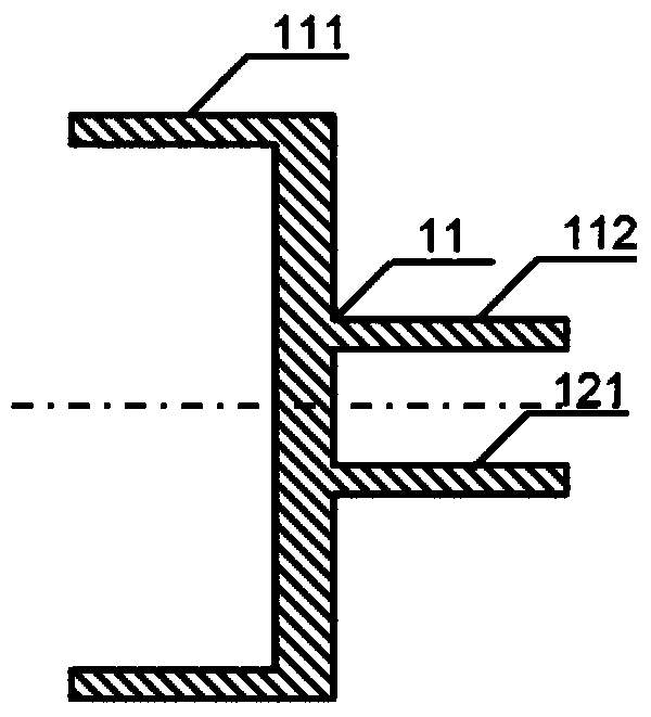
[0061] figure 1 As shown, there is a push piston 111 in the push piston body 11, a push piston rod 112, and a push piston shaft mounting hole 121. Push the piston 111, push the piston rod 112, and push the piston shaft mounting hole 121 to ensure sufficient coaxiality.

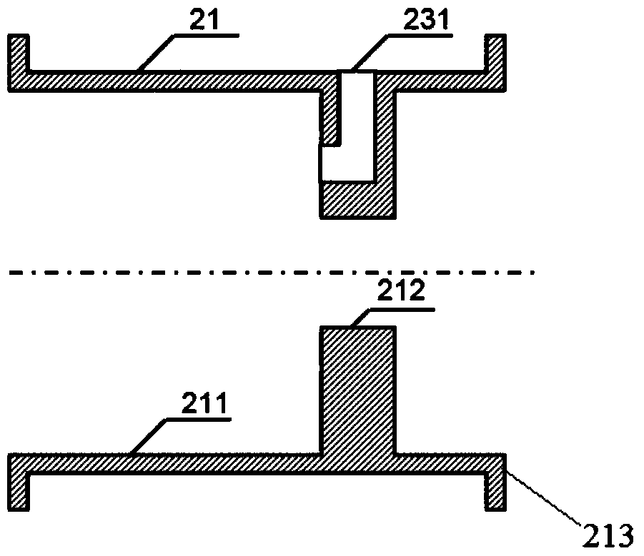
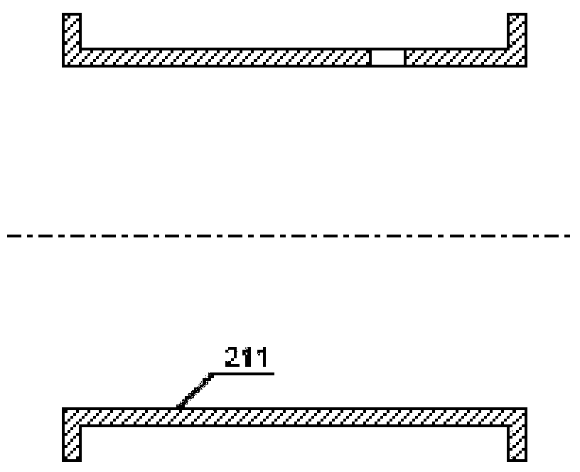
[0062] figure 2 As shown, there is a moving piston cylinder 211 in the moving piston cylinder body 21, a moving piston rod hole 212, a moving piston cylinder installation port 213 and a back cavity port 231. Push the piston cylinder 211, push the piston rod hole 212, and push the piston cylinder installation port 213 to ensure sufficient coaxiality.

[0063] Because in the actual processing process, the push piston cylinder body 21 is processed once, and the coaxiality of the push piston cylinder 211, the push piston rod hole 212 and the push piston cylinder mounting port 213 is also considered, which is difficult. Therefore, the push piston cylinder body 21 can be processed separately, that is, the push p...

Embodiment 2

[0071] Figure 10 It is a multi-stage stepped push piston system, wherein the multi-stage stepped push piston is made hollow and has a pressure balance hole 113, so that the mass of the multi-step stepped push piston can also be used as the volume of the gas storage, such as Figure 8 As shown, the multi-stage step type push piston has a first push piston 141, a second push piston 142 and a third push piston 143, and the second push piston 142, the third push piston 143 and the first push piston 141 keep coaxial as far as possible Spend. Figure 9 Among them, the second push piston cylinder 212 and the third push piston cylinder 213 are respectively arranged between the front end cover 22 of the push piston cylinder block and the second push piston 142 and the third push piston 143, and the two should keep sufficient coaxiality as far as possible. Spend.

[0072] Wherein, the moving piston cylinder 211 (which can be regarded as the first moving piston cylinder in this embodi...

Embodiment 3

[0075] Figure 13 It is a reverse E-type push piston system, wherein the push piston 111 is a reverse E-type piston, such as Figure 11 shown; Figure 12 Push Piston Cylinder Block Front Cover shown for use with Reverse E-Type Pistons; as Figure 13 As shown, in the anti-E type push piston system, a first push piston front chamber 221a and a second push piston front chamber 221b are provided, and the first push piston front chamber 221a has a first push piston front cavity port 232a, and the second push piston front chamber The front chamber 221b has a second push piston front chamber port 232b. All the other structures are the same as in Example 1.

[0076] Figure 13-1 It is a structural schematic diagram of the reverse E-type moving piston system used in a multi-stage pulse tube refrigerator in this embodiment. The freezing part 40 is composed of a cooler 41, a first-stage regenerator 42a, a first-stage cold head 43a and a first-stage pulse tube 44a; and the first-stag...


PUM


Abstract

The invention relates to a pushing piston system and an application of the pushing piston system in a pulse tube refrigerator. The pushing piston system comprises a pushing piston body and a pushing piston air cylinder body which are coaxially assembled. The pushing piston body comprises a pushing piston, a pushing piston rod and a pushing piston shaft assembly which are coaxially arranged. The pushing piston shaft assembly comprises a pushing piston shaft, a leaf spring fixing partition plate and a leaf spring which connects the pushing piston shaft with the leaf spring fixing partition plate. The leaf spring partition plate is provided with an installation boss. The pushing piston, the pushing piston rod, the pushing piston shaft and the installation boss are coaxially arranged. The pushing piston air cylinder body comprises a pushing piston air cylinder, a pushing piston rod hole and a pushing piston air cylinder installation opening, wherein the pushing piston rod hole and the pushing piston air cylinder are coaxially arranged. Compared with the prior art, the pushing piston system is simple in structure and convenient to assemble, can ensure the coaxiality and then ensures the effects that the pushing piston is in clearance sealing with the pushing piston air cylinder, and the pushing piston rod is in clearance sealing with the pushing piston rod hole.

Description

technical field [0001] The invention belongs to the technical field of refrigerators, and relates to a moving piston system and its application in pulse tube refrigerators. Background technique [0002] A pulse tube refrigerator is a low temperature refrigerator. The room temperature moving piston pulse tube refrigerator is one of the most theoretically efficient pulse tube refrigerators. In moving piston pulse tube refrigerators at room temperature, in order to achieve long life, gap seals are generally used. In the gap-sealed push piston system, because the structure is concave, the gap between the push piston and the push piston cylinder and the gap between the push piston rod and the push piston rod hole are difficult to guarantee. The traditional manufacturing method is to push the piston rod through the hole of the push piston rod and insert it into the air storage, the push piston rod is installed on the leaf spring in the air storage, the leaf spring is fixed on th...

Claims


Application Information

Patent Timeline
Patent Type & Authority Patents(China)
IPC IPC(8): F25B9/14F25B1/00
CPCF25B1/00F25B9/145
Inventor 朱绍伟
Owner TONGJI UNIV
Features
  • R&D
  • Intellectual Property
  • Life Sciences
  • Materials
  • Tech Scout
  • Unparalleled Data Quality
  • Higher Quality Content
  • 60% Fewer Hallucinations
Learn More