Cutting device and method for composite substrate

A composite substrate and cutting device technology, applied in welding equipment, laser welding equipment, metal processing equipment, etc., can solve the problems of large cutting edge taper, large ablation width of ink coating, etc., to achieve small edge taper, reduce The effect of ablation width and depth of focus

Inactive Publication Date: 2017-08-11
东莞市盛雄激光先进装备股份有限公司
View PDF8 Cites 15 Cited by
  • Summary
  • Abstract
  • Description
  • Claims
  • Application Information

AI Technical Summary

Problems solved by technology

[0005] In view of this, the present invention provides a cutting device and cutting method for a composite substrate to solve the problems in the prior art that the cutting edge of the composite substrate has a relatively large taper and the ablation width of the ink coating is too large

Method used


Image

  • Cutting device and method for composite substrate
  • Cutting device and method for composite substrate
  • Cutting device and method for composite substrate

Examples


Embodiment Construction

[0058] The technical solutions in the embodiments of the present invention will be clearly and completely described below in conjunction with the accompanying drawings in the embodiments of the present invention. Obviously, the described embodiments are only a part of the embodiments of the present invention, rather than all the embodiments. Based on the embodiments of the present invention, all other embodiments obtained by those of ordinary skill in the art without creative work shall fall within the protection scope of the present invention.

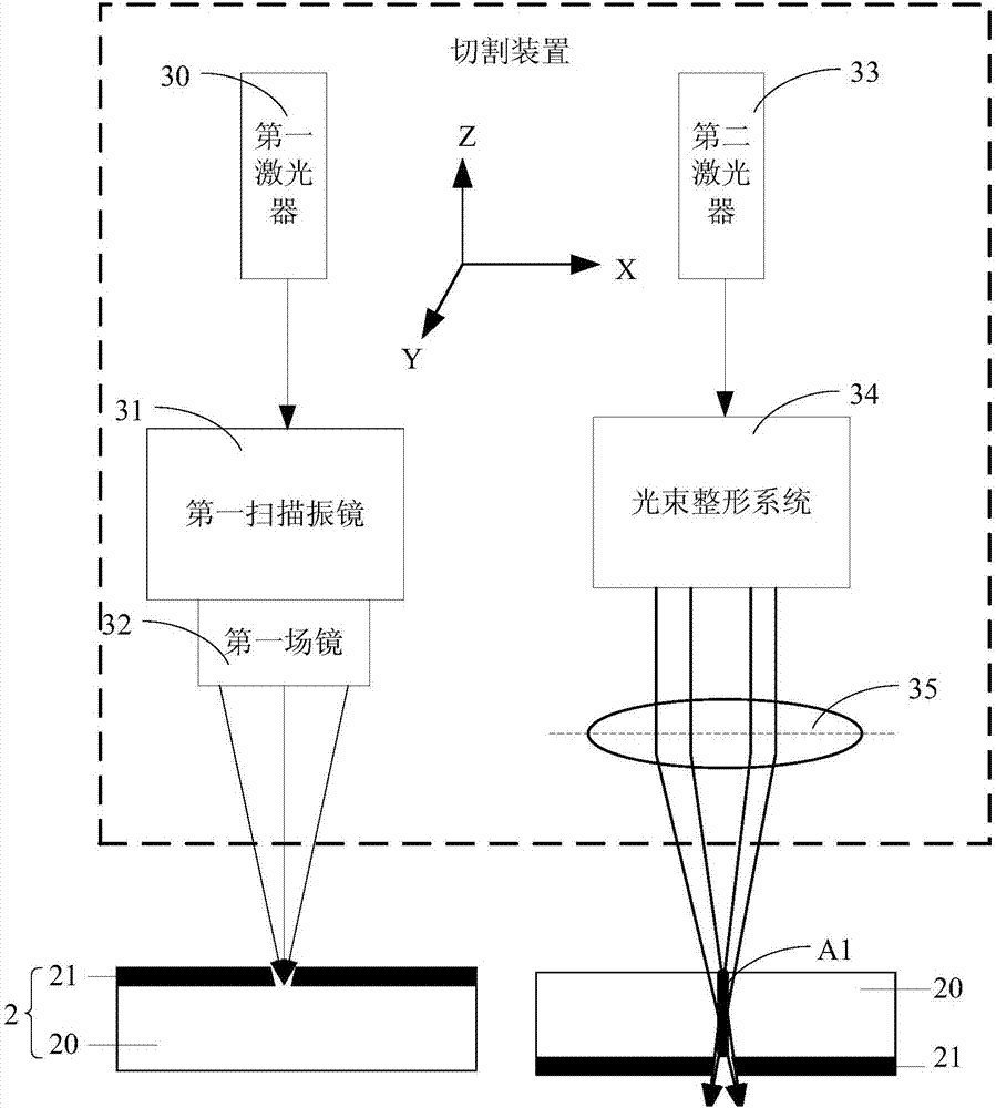
[0059] The embodiment of the present invention provides a cutting device for a composite substrate, such as figure 2 As shown, the composite substrate 2 includes a transparent substrate 20 and an ink coating 21 on the surface of the transparent substrate 20. The cutting device includes a first laser 30 and a first scanning galvanometer 31 sequentially arranged on the light path of the first laser 30. And the first field lens 32, the seco...


PUM

PropertyMeasurementUnit
diameteraaaaaaaaaa
lengthaaaaaaaaaa

Abstract

The invention provides a cutting device and method for a composite substrate. The composite substrate comprises a transparent base and a printing ink coating. The cutting device comprises a first laser device, a first scanning galvanometer, a first field lens, a second laser device, a beam shaping system and a first condenser lens; first laser is emitted from the first laser device, reflected by the first scanning galvanometer and focused by the first field lens, so that the first laser erodes the printing ink coating along preset cutting lines and light transmitting lines are formed; second laser is emitted from the second laser device, and is a gauss beam; the beam shaping system converts the gauss beam into a bessel beam; the bessel beam is focused by the first condenser lens, so that the bessel beam pre-cuts the transparent base along the light transmitting lines; and the erosion width of the printing ink coating and the edge conicity of the composite substrate can be reduced.

Description

Technical field [0001] The invention relates to the technical field of laser cutting, and more specifically, to a cutting device and a cutting method for a composite substrate. Background technique [0002] With the development of science and technology, transparent materials such as glass, sapphire, ceramics, etc. have been widely used in consumer electronics fields such as fingerprint identification buttons, camera protection lenses, tablets and smart phone screens. [0003] Before applying the transparent material to the product, the transparent material needs to be cut. Since transparent materials have the characteristic of high hardness, lasers are mostly used in the prior art to cut transparent materials. Such as figure 1 As shown, after the Gaussian beam emitted by the picosecond laser 10 is reflected by the high-speed displacement scanning galvanometer 11, it is focused on the surface of the transparent material 13 by the field lens 12, and then the focused beam repeats mo...

Claims


Application Information

Patent Timeline
Patent Type & Authority Applications(China)
IPC IPC(8): B23K26/38B23K26/402B23K26/064
CPCB23K26/38B23K26/064B23K26/0652B23K26/402
Inventor 陶雄兵李万朋
Owner 东莞市盛雄激光先进装备股份有限公司
Why Eureka
Try Eureka