Conveyor

A technology of conveying device and running body, which is applied in conveyors, mechanical conveyors, transportation and packaging, etc., and can solve the problem that the screw drive method is not known

Active Publication Date: 2019-02-19
DAIFUKU CO LTD
View PDF5 Cites 0 Cited by
  • Summary
  • Abstract
  • Description
  • Claims
  • Application Information

AI Technical Summary

Problems solved by technology

[0007] However, when there is an inclined path portion in the travel path, a screw drive method is not known as a driving means for propelling the transport body in the inclined path portion.

Method used


Image

  • Conveyor
  • Conveyor
  • Conveyor

Examples


Embodiment Construction

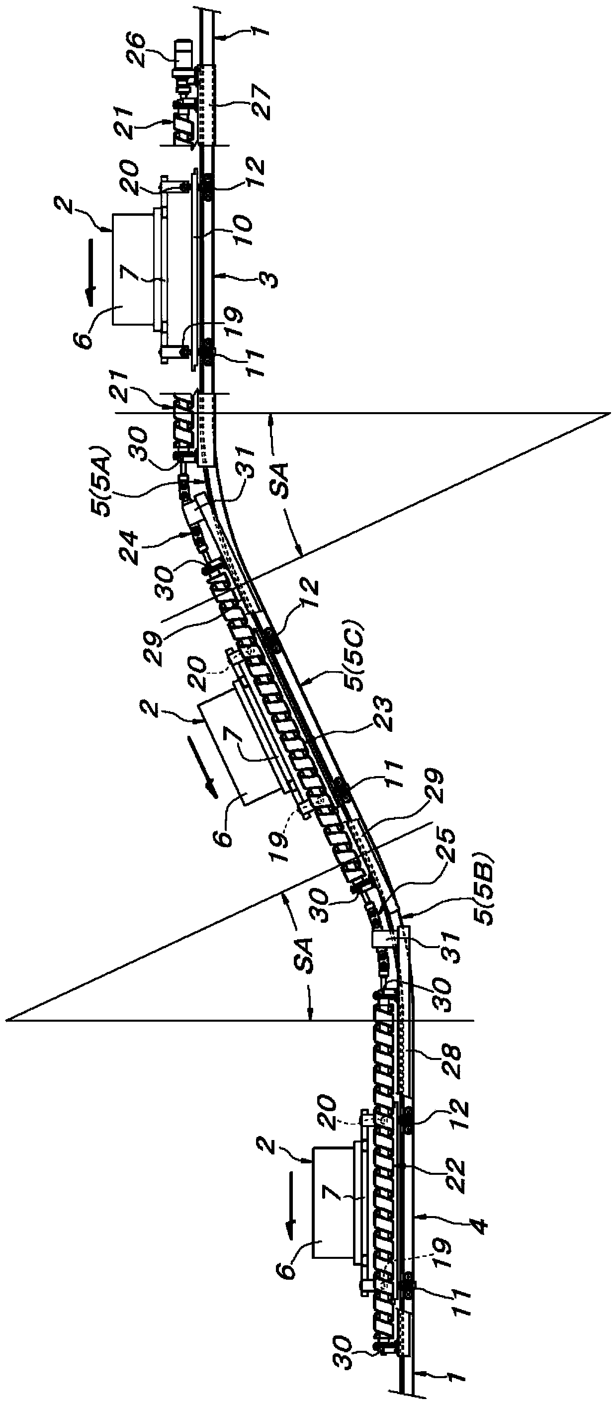
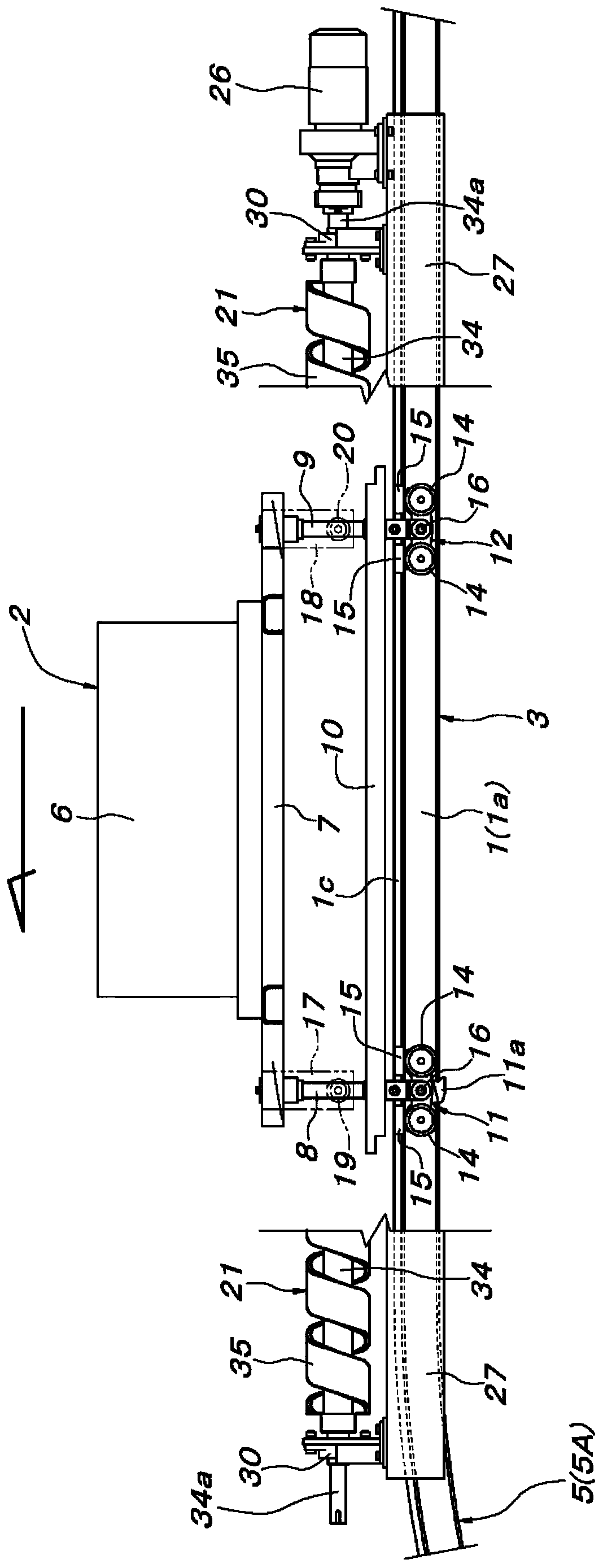
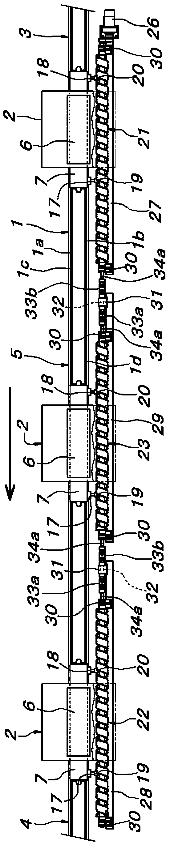
[0056] based on Figure 1~6 Referring to the first embodiment, an inclined path portion 5 connecting the upper horizontal path portion 3 and the lower horizontal path portion 4 is provided on the traveling path of the transport traveling body 2 constituted by the guide rail 1 . In this embodiment, the transport running body 2 travels from the upper horizontal path portion 3 to the lower horizontal path portion 4 via the inclined path portion 5 . The traveling body 2 for conveying is made up of the following components: a long main body 7 in the forward and backward travel direction, and the main body 7 is provided with a conveyed object supporting part 6 on the upper side; The pillar members 8 and 9 are connected to be vertically downward from the central position in the width direction of the front and rear ends of the main body 7; the load rod 10 for friction driving is mounted on the front and rear pair of supporting pillar members. 8, 9 in the vicinity of the lower end an...


PUM


Abstract

A conveying device has interlockingly coupled, rectilinear screw shafts which are driven by a motor. The screw shafts are juxtaposed to an inclined rectilinear portion of a gradient portion in a traveling route of a conveying traveling body and to at least fixed regions adjacent to the gradient portion of respective upper and lower horizontal route portions connected to respective ends of the gradient portion. The conveying traveling body has a pair of front and rear driven rollers engaging with the screw shafts, and an interval between the pair of front and rear driven rollers is set to a length not shorter than a rectilinear distance between end portions of the screw shafts positioned at respective sides of each of arcuate portions at respective upper and lower ends of the gradient portion to make the conveying traveling body travel continuously between the respective upper and lower horizontal route portions.

Description

technical field [0001] The present invention relates to a conveying device. The conveying device propels the traveling body for conveying along a traveling path through a screw shaft and driven rollers, wherein the screw shaft is arranged in parallel on the traveling path of the traveling body for conveying, and the driven rollers are arranged in parallel with the traveling path of the traveling body for conveying. This screw shaft is pivotally supported on the conveyance traveling body in an engaged manner. Background technique [0002] A conveying device of a screw drive type known, for example, from Patent Document 1, etc., which propels a traveling body for conveyance along a travel path through a screw shaft and driven rollers driven by a motor, wherein the motor The driving screw shaft is arranged in parallel along the travel path, and the driven roller is pivotally supported by the transport traveling body so as to engage with the screw shaft. [0003] prior art lite...

Claims


Application Information

Patent Timeline
Patent Type & Authority Patents(China)
IPC IPC(8): B61B13/12B65G35/06
CPCB65G35/066B65G21/22B65G33/04B65G33/32B65G35/00B65G35/06
Inventor 京谷尚士
Owner DAIFUKU CO LTD
Why Eureka
Try Eureka