Horizontal electromagnetic pulling type safety braking device for gear and rack driven lifting equipment

A technology of lifting equipment and rack and pinion is applied in the field of safety braking device of lifting equipment, which can solve the problems of inability to guarantee reliable braking and the like

Active Publication Date: 2017-08-11
TAICANG DENASEN MECHANICAL & ELECTRICAL ENG CO LTD
View PDF5 Cites 4 Cited by
  • Summary
  • Abstract
  • Description
  • Claims
  • Application Information

AI Technical Summary

Problems solved by technology

[0002] The power device of the rack and pinion lifting equipment is installed on the equipment car. How to reduce the weight of the device is a task that requires continuous efforts; the existing safety brake device of the rack and pinion lifting equipment uses various methods to make the drive gear However, if there is a p

Method used


Image

  • Horizontal electromagnetic pulling type safety braking device for gear and rack driven lifting equipment
  • Horizontal electromagnetic pulling type safety braking device for gear and rack driven lifting equipment
  • Horizontal electromagnetic pulling type safety braking device for gear and rack driven lifting equipment

Examples


Embodiment 1

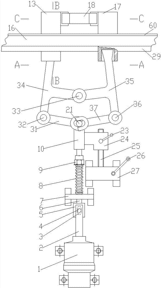
[0019] Example 1, Figure 8 It is a schematic diagram of embodiment 1, and the drawing shows the appearance of the side of the lifting equipment. The horizontal electromagnetic pulling safety brake device is installed on the top of the rack and pinion lifting equipment, temporarily in a free position, and the lifting equipment is ready to run or is running In the situation, Figure 9 It is a schematic diagram of the situation that the horizontal electromagnetic pulling safety braking device of embodiment 1 brakes the lifting equipment, (the front figure 1 , figure 2 , image 3 , Figure 4 , Image 6 , Figure 7 The left and right mentioned are viewed from the inside of the lifting device to the side of the lifting device. Figure 8 , Figure 9 It is viewed from the outside to the side of the lifting equipment, so the left and right directions are just in reverse). Figure 1-7 As shown in paragraphs [0004], [0005], [0006] and [0007], due to the coordination and coordin...

Embodiment 2

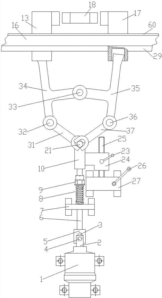
[0020] Example 2, Figure 8 , Figure 9 It is also a schematic diagram of embodiment 2, which shows an elevator equipped with the horizontal electromagnetic pull safety braking device of the present invention, and a description of the components and functions of the internal structure of the horizontal electromagnetic pull safety brake device used See Figure 1-7 As shown, and described in [0004], [0005], [0006], and [0007], the working principle is the same as that described in [0019].


PUM


Abstract

The invention relates to a horizontal electromagnetic pulling type safety braking device for gear and rack driven lifting equipment. The horizontal electromagnetic pulling type safety braking device comprises a load-bearing part, a track component, movable racks, a limiting mechanism of the movable racks, a control mechanism of the movable racks, a control device of the control mechanism of the movable racks and a manual unlocking mechanism which are configured in the horizontal direction, wherein after the horizontal electromagnetic pulling type safety braking device enters the braking state, the tops of the movable racks are in direct contact with the main load-bearing structure of the lifting equipment cage, or in contact with the main load-bearing structure of the lifting equipment cage through a middle transition load-bearing part for load bearing; the control mechanism of the movable racks configured in the horizontal direction controls the movable racks to perform horizontal movement on the track component or remain at the braking position where the movable racks are meshed with driving racks of the lifting equipment or at a free position where the movable racks and the driving racks of the lifting equipment are totally separated and spaced by an interval; the self weight of the device is reduced by adopting an electromagnetic pulling device, and the benefits of reducing the self weight, economizing the effective space, obviously improving the leveling accuracy and the safety protection braking quality are achieved.

Description

technical field [0001] The invention relates to the field of safety braking devices for lifting equipment, in particular to a horizontal electromagnetic pulling safety braking device for rack and pinion lifting equipment. Background technique [0002] The power device of the rack and pinion lifting equipment is installed on the equipment car. How to reduce the weight of the device is a task that requires continuous efforts; the existing safety brake device of the rack and pinion lifting equipment uses various methods to make the drive gear However, if there is a problem with the drive gear, such as a damaged gear, reliable braking cannot be guaranteed even if the gear does not rotate; in order to ensure safety, the rack and pinion lifting equipment must be equipped with a reliable device that can deal with problems including the drive gear. And safety brakes for similar safety issues. Contents of the invention [0003] The object of the present invention is to provide a s...

Claims


Application Information

Patent Timeline
IPC IPC(8): B66D5/30B66B5/16
CPCB66B5/16B66D5/30
Inventor 廖忠民
Owner TAICANG DENASEN MECHANICAL & ELECTRICAL ENG CO LTD
Why Eureka
Try Eureka