A construction fence for civil engineering

A technology of civil engineering and fencing, applied in the direction of buildings, fences, building types, etc., can solve problems such as construction waste, unstable bottom, troublesome disassembly, etc., and achieve the effects of enhanced wind resistance, easy assembly, and simple structure

Inactive Publication Date: 2019-03-26
李怡坤
View PDF4 Cites 0 Cited by
  • Summary
  • Abstract
  • Description
  • Claims
  • Application Information

AI Technical Summary

Problems solved by technology

After the construction of this kind of wall is completed, it is troublesome to dismantle it. It needs to use excavators to dismantle it. The materials after dismantling cannot be reused and form construction waste, which is not conducive to environmental protection.
[0003] Another simple iron fence is only supported by supporting legs, and the bottom is unstable. When the wind is strong or encounters an impact, it is easy to fall sideways and become a safety hazard.

Method used


Image

  • A construction fence for civil engineering
  • A construction fence for civil engineering
  • A construction fence for civil engineering

Examples


Embodiment 1

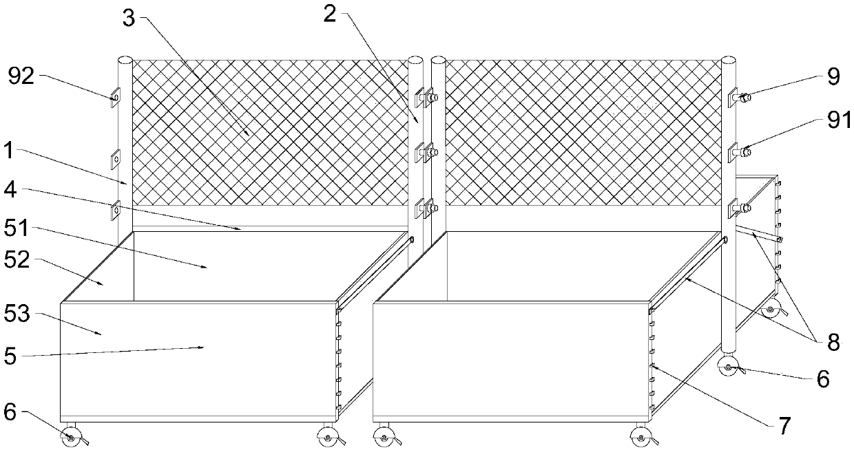
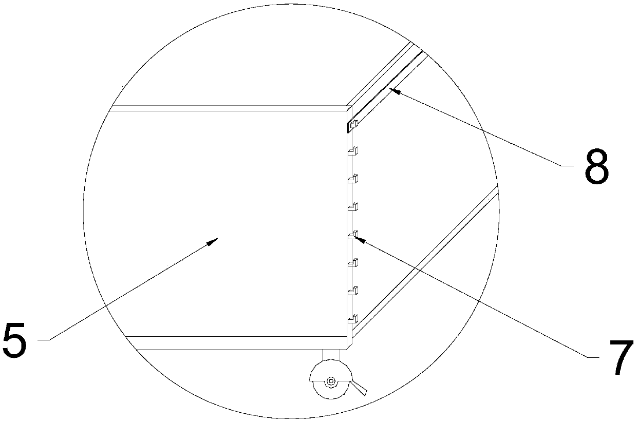
[0022] Such as figure 1 , figure 2 , image 3 The shown construction fence for civil engineering includes a fence main body and a box body 5. The fence main body includes a first column 1, a second column 2, a shielding plate 3, and a transverse support rod 4. The first column 1 and the A plurality of transverse support rods 4 are arranged between the second uprights 2, and a shading plate 3 is arranged between the first upright 1 and the second upright 2, and the shading plate 3 is located between the first upright 1 and the second upright 2. Partially above, the first column 1 is provided with a connecting block 92, the second column 2 is provided with a connecting bolt 9, and the connecting bolt 9 is provided with a fastening nut 91, and the connecting bolt 9 can pass through the connection on the connecting block 92. hole, then fix with fastening nut 91, two described fence main bodies are connected together, described fence main body both sides are provided with box bo...

Embodiment 2

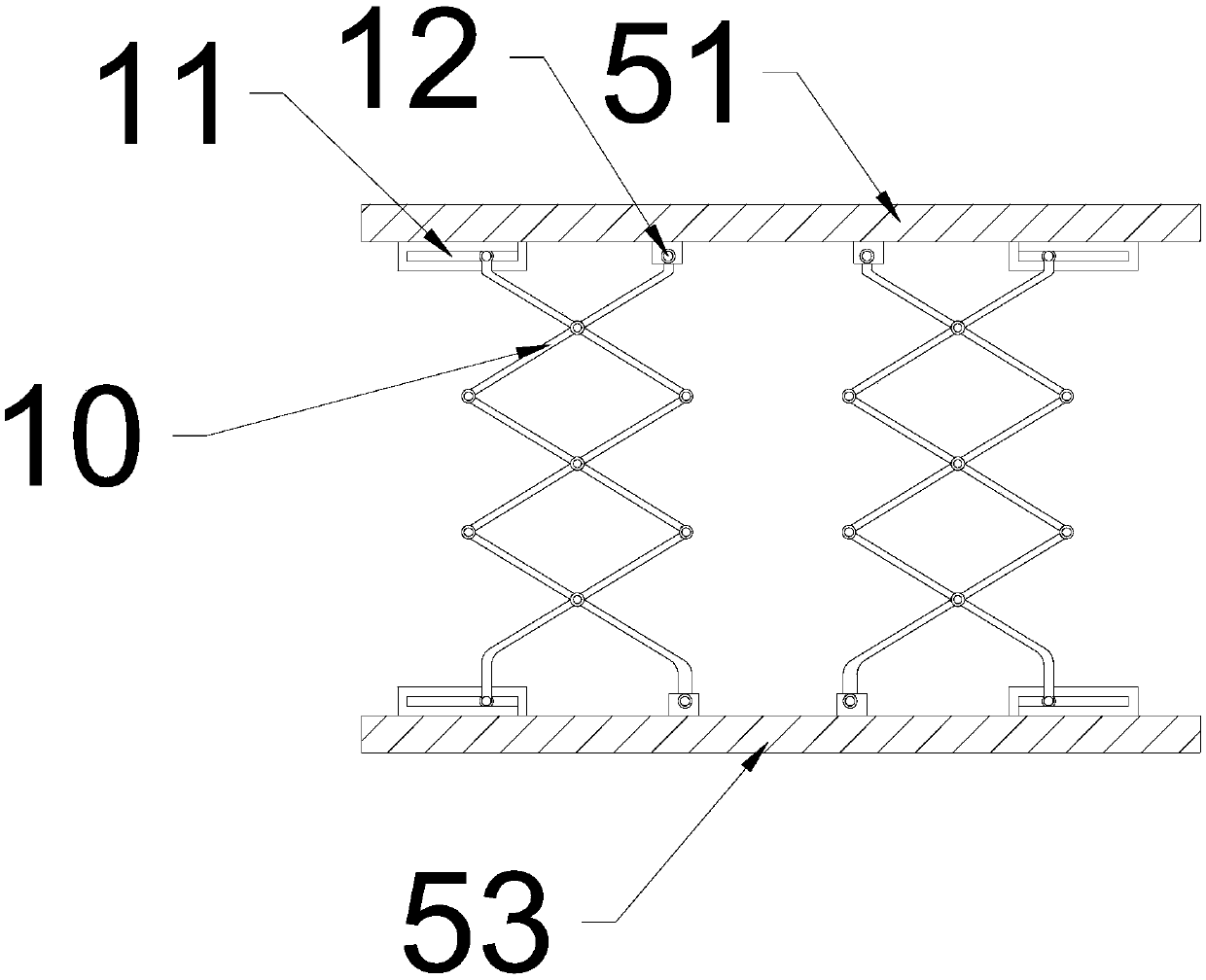
[0031] Specifically, the telescopic assembly includes guide rails 14, a plurality of supporting plates 13, the supporting plates 13 are parallel to the connecting plate 51, between the supporting plate 13 and the connecting plate 51, between the supporting plate 13 and the supporting plate 53, The adjacent two supporting plates 13 are all equipped with a shearing assembly, and the shearing assembly is provided with a pair of supporting rods 10 crossing each other, and the assembly method is as follows: Figure 5 As shown, as the assembly mode of the shearing assembly between the supporting plate 13 and the connecting plate 51: one end of one of the support rods 10 is provided with a guide slider, and the guide slider is assembled into the guide track 14 on the connecting plate 51, and the support rod The other end of 10 is hinged on the pallet 13 through a hinge, and one end of the other support rod 10 is provided with a guide slider, which is assembled into the guide track on ...


PUM


Abstract

The invention relates to an architecture fencing for civil engineering. The fencing comprises a fencing main body and case bodies, wherein the fencing main body includes a first stand column, a second stand column, a baffle plate and lateral bracings; a plurality of the lateral bracings are arranged between the first stand column and the second column; the baffle plate is mounted between the first stand column and the second stand column; the first stand column is provided with link blocks, and the second stand column is provided with connecting bolts which is provided with tight nuts; both sides of the fencing main body are provided with the case bodies; universal wheels with brake apparatuses are arranged on bottoms of the first stand column, the second stand column and the case bodies. The architecture fencing of simple structure has the advantages that the universal wheels positioned at the bottoms are convenient for assembly; the design of the case bodies is capable of balancing weight of the bottom of the fencing main body to strengthen capability of resisting wind; since the case bodies are flexible, the function of adjusting the occupied areas of the case bodies according to different terrain areas can be realized.

Description

technical field [0001] The invention relates to the field of civil engineering, in particular to a building fence for civil engineering. Background technique [0002] During the construction process in civil engineering, the construction site is generally dangerous. The fence is to isolate the construction site from the external environment, making the construction site a relatively closed space. Conventional building fences are made of various masonry materials. , Fences made of plates, etc. After the construction of this kind of wall is completed, it is troublesome to dismantle it, and it is necessary to use excavators to dismantle it. The materials after dismantling cannot be reused and form construction waste, which is not conducive to environmental protection. [0003] Another kind of simple iron fence is only supported by supporting legs, and the bottom is unstable. When the wind is strong or encounters impact, it is easy to fall sideways and become a safety hazard. ...

Claims


Application Information

Patent Timeline
Patent Type & Authority Patents(China)
IPC IPC(8): E04H17/14
CPCE04H17/14
Inventor 李怡坤
Owner 李怡坤
Why Eureka
Try Eureka