Dressing change cart for medical care

A cart and push rod technology, applied in the field of medical care, can solve the problems such as the inability to control the bending angle of the patient's legs, the large size of the dressing rack, and the occupation of space, and achieves good dressing effect, convenient operation and simple installation. Effect

Inactive Publication Date: 2020-09-25
湖南弘烨医疗器械有限公司
View PDF11 Cites 0 Cited by
  • Summary
  • Abstract
  • Description
  • Claims
  • Application Information

AI Technical Summary

Problems solved by technology

[0004] Although the above-mentioned dressing change stand can make the patient's legs rise, when it rises to a certain height, it will bring discomfort to the patient, and the above-mentioned dressing change stand cannot control the bending angle of the patient's legs, and when the dressing change is completed, the changing The medicine rack is bulky and takes up space

Method used


Image

  • Dressing change cart for medical care
  • Dressing change cart for medical care
  • Dressing change cart for medical care

Examples


Embodiment 1

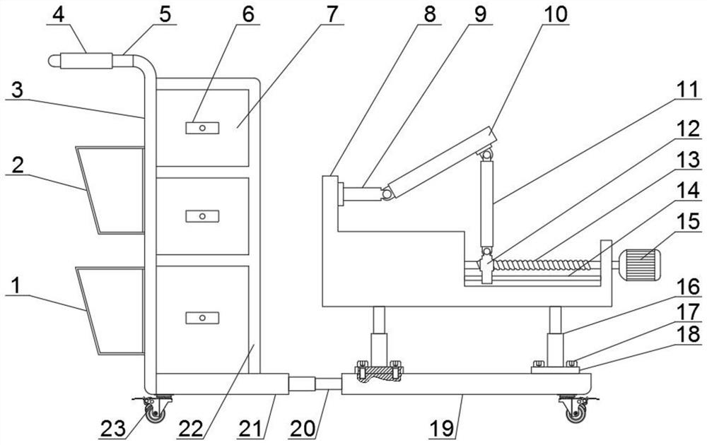
[0025] see Figure 1-3 , a medicine changing trolley for medical care, comprising a first base plate 19, a second hydraulic rod 20 is fixedly connected to the left side of the first base plate 19, and a second base plate 21 is fixedly connected to the left side of the second hydraulic rod 20, so The left side of the second bottom plate 21 is fixedly connected with a push rod 3, and the upper part of the push rod 3 is fixedly connected with a hand lever 5, which is convenient for pushing. The first bottom plate 19 and the bottom of the second bottom plate 21 are equipped with running wheels 23, and the running wheels 23 are universal wheels with brakes, which are convenient for installation and fixing, and are easy to use. The top of the second bottom plate 21 is fixedly connected with a mounting bracket 22 , the inside of the installation frame 22 is fixedly connected with a number of storage boxes 6, the surface of the storage box 6 is provided with a handle 7, the upper part...

Embodiment 2

[0027] In another embodiment of the present invention, the difference between this embodiment and the above-mentioned embodiment is that the lower part of the left side of the push rod 3 is fixedly connected with the first dustbin 1, and the upper part of the first dustbin 1 is installed with a second dustbin. The dustbin 2, the first dustbin 1 and the second dustbin 2 are convenient for sorting the waste.

[0028] The working principle of the present invention is: hold the spacer 4, push the push rod 3, push the cart to the side of the patient, extend the second hydraulic rod 20, place the patient's legs on the top of the first support rod 10, and adjust the The first hydraulic rod 16 and the drive motor 15 adjust the height and angle of the patient's legs so that the patient is in a comfortable position, take out the medicine that needs to be dosed from the storage box 6, and throw the rubbish into the first dustbin 1 and the second dustbin. Second trash can 2, after changin...


PUM


Abstract

The invention discloses a dressing change cart for medical care, and belongs to the field of medical care. The dressing change cart for medical care comprises a first bottom plate, wherein a second hydraulic rod is fixedly connected to the left side of the first bottom plate; a second bottom plate is fixedly connected to the left side of the second hydraulic rod; traveling wheels are mounted on the lower portions of the first bottom plate and the second bottom plate respectively; a plurality of fixing plates are fixedly connected to the upper portion of the first bottom plate; locking screws are in threaded connection with the first bottom plate and the fixing plates; a first hydraulic rod is fixedly connected to the upper portions of the fixing plates; a mounting base is mounted on the upper portion of the first hydraulic rod; a ball screw is rotationally connected to the middle of the mounting base; a driving motor is fixedly connected to the right side of the ball screw; a movable block is in threaded connection with the middle of the ball screw; an optical shaft is in sliding connection with the lower portion of the movable block; a second supporting rod is hinged to the upperportion of the movable block; and a first supporting rod is hinged to the upper portion of the second supporting rod. The dressing change cart is simple in structure, high in practicability, high in dressing change effect and worthy of application and popularization.

Description

technical field [0001] The invention relates to the field of medical care, in particular to a dressing trolley for medical care. Background technique [0002] With the development and progress of society and the improvement of people's living standards, the demand for nurses is increasing, and the requirements are getting higher and higher. More and more migrant workers have entered the nursing industry. In hospitals, communities or families, many patients have accepted the services provided by nursing workers. When the nurses change the dressing for the patient, they need to use the dressing trolley. [0003] Existing authorized announcement number is that the Chinese patent of CN209916503U discloses a kind of medical nursing dressing changing stand, comprises base plate, and one side of described base plate top is fixedly connected with cabinet, and the other side of base plate top is fixedly connected with box, so Both sides of the top of the bottom plate and both sides...

Claims


Application Information

Patent Timeline
Patent Type & Authority Applications(China)
IPC IPC(8): A61G12/00A61G7/075
CPCA61G7/0755A61G12/001
Inventor 曹立
Owner 湖南弘烨医疗器械有限公司
Why Eureka
Try Eureka