Array laser radar light splitting device and method

A spectroscopic device and array technology, applied in the field of optical transmission, can solve the problems of low frequency, low safety threshold of human eyes, asynchronous light source, etc., and achieve the effect of broad application prospects

Inactive Publication Date: 2017-08-11
O NET COMM (SHENZHEN) LTD
View PDF3 Cites 4 Cited by
  • Summary
  • Abstract
  • Description
  • Claims
  • Application Information

AI Technical Summary

Problems solved by technology

At present, most laser radar light sources use semiconductor lasers with a wavelength of 905nm, but their frequency is low and the safety threshold of human eyes is low, and the light source adopts an asynchronous working mode when scanning.

Method used


Image

  • Array laser radar light splitting device and method
  • Array laser radar light splitting device and method

Examples


Embodiment Construction

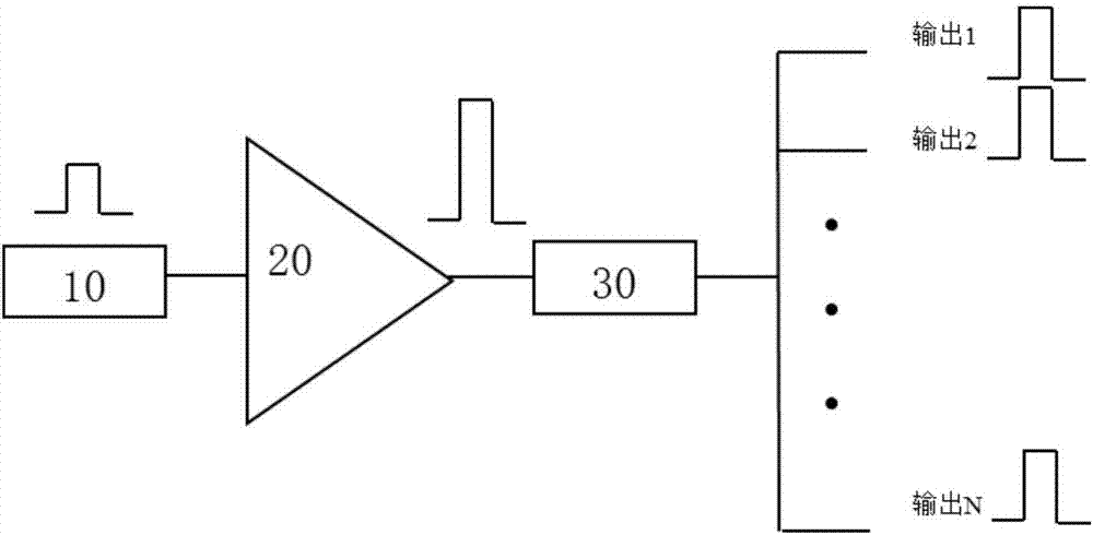
[0025] like figure 1 Shown is a schematic structural diagram of the first embodiment of the array type light source beam splitting device of the present invention. The array type light source beam splitting device of the present invention includes a seed source 10 as input signal light, and a fiber amplifier 20 connected to the seed source 10. , and an optical splitter 30 connected to the optical fiber amplifier 20 , the optical splitter 30 is provided with N optical fibers, and N is a natural number.

[0026] The N optical fibers are the first optical fiber, the second optical fiber, the third optical fiber, ... and the Nth optical fiber arranged in parallel.

[0027] The seed source 10 uses a laser with a wavelength of 1550 nanometers. The optical fiber amplifier 20 is provided with rare-earth-doped elements, that is, the rare-earth-doped elements in the optical fiber amplifier 20 realize 1550 nm signal light amplification. The optical splitter 30 divides the signal light ...


PUM


Abstract

The invention relates to an array light source light splitting device and method. The device comprises a seed source for inputting signal light, fiber amplifiers connected with the seed source, and a light splitter connected with the fiber amplifiers, wherein the light splitter is provided with N paths of fibers, the N is a natural number, and the signal light of the seed source is split by the light splitter into N paths which are outputted. According to the device, the signal light of the seed source is split by the light splitter into the N paths which are outputted, the N paths of signal light are amplified through the amplifier of each branch for power amplification, and multiple paths of signal light are outputted; repetition frequency of 1550 nanometer laser can reach megahertz, so the laser has a relatively high water absorption coefficient, when the laser in with the wave band radiates to eyes, an eye damage threshold is relatively high, but the wave band laser of the device has eye safety characteristics; a synchronization work mode can be employed in a light source, and the device has wide application prospects in the automatic driving and 3D scanning field.

Description

technical field [0001] The invention belongs to the technical field of optical transmission, and in particular relates to an array light source light splitting device and a light splitting method thereof. Background technique [0002] Lidar is a radar system that emits laser beams to detect the position, velocity and other characteristic quantities of targets. At present, most of the laser radar light sources use semiconductor lasers with a wavelength of 905 nm, but their frequency is low and the safety threshold for human eyes is low, and the light source adopts an asynchronous working mode during scanning. SUMMARY OF THE INVENTION [0003] The purpose of the present invention is to provide an array type light source light splitting device and a light splitting method which adopts a synchronous working mode and outputs multiple signal light outputs. [0004] The invention provides an array type light source light splitting device, which comprises: a seed source of input ...

Claims


Application Information

Patent Timeline
Patent Type & Authority Applications(China)
IPC IPC(8): G02B6/12G02B6/42
CPCG02B6/12G02B6/425G02B2006/1215H01S3/1603H01S3/06754H01S3/2383H01S5/4025
Inventor 鲁开源华一敏
Owner O NET COMM (SHENZHEN) LTD
Why Eureka
Try Eureka