
Commutation Failure Analysis Method for DC Transmission Considering Harmonic Effect

A technology of commutation failure and harmonic influence, applied to harmonic reduction devices, AC networks to reduce harmonics/ripples, electrical components, etc., can solve problems such as commutation failure, overcome excessive calculation errors, and realize Quantitative analysis, the effect of improving calculation accuracy

Active Publication Date: 2020-05-08
TIANJIN UNIV
View PDF4 Cites 0 Cited by
  • Summary
  • Abstract
  • Description
  • Claims
  • Application Information

AI Technical Summary

Problems solved by technology

The present invention first proposes a calculation formula for the turn-off angle of the inverter side converter taking into account the influence of harmonics. This formula also considers the influence of DC current changes and harmonics on the commutation process after the inverter side AC system fails, and overcomes the traditional The calculation formula of turn-off angle cannot reflect the shortcoming that the turn-off angle decreases at the initial stage of the fault, and using this formula and the ideal critical commutation voltage value, a method for judging whether the commutation of the DC system fails after the AC system fault on the inverter side is proposed, and the inverter Quantitative analysis of the influence of harmonics on commutation failure after side AC system fault

Method used


Image

  • Commutation Failure Analysis Method for DC Transmission Considering Harmonic Effect
  • Commutation Failure Analysis Method for DC Transmission Considering Harmonic Effect
  • Commutation Failure Analysis Method for DC Transmission Considering Harmonic Effect

Examples


Embodiment Construction

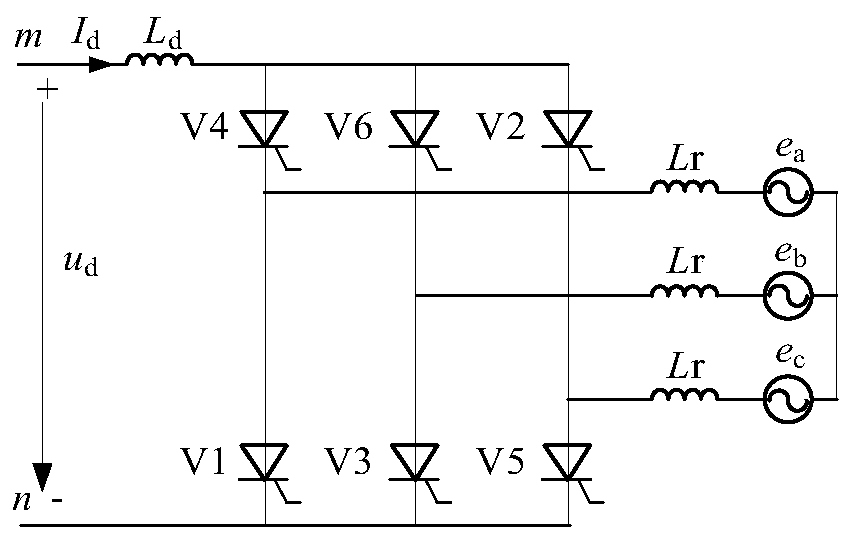
[0027] The commutation failure analysis method considering the influence of harmonics of the present invention consists of the following steps:

[0028] (1) Obtain the inherent limit turn-off angle γ according to the traditional calculation formula of turn-off angle γ min Corresponding commutation voltage U CR , define U CR is the ideal critical commutation voltage value.

[0029] (2) When the commutation voltage U LL below U CR When , the commutation failure must occur in the DC system, namely:

[0030] u LL ≤ U CR commutation failure

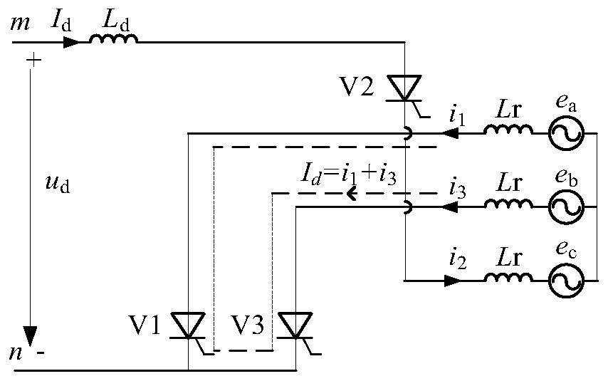
[0031] (3) When the commutation voltage U LL greater than U CR , commutation failure may also occur in the DC system. Utilize the cut-off angle calculation formula proposed by the present invention and the influence of harmonics to calculate the minimum value of the initial cut-off angle of the AC system fault on the inverter side, expressed by γ k ,which is:

[0032]

[0033] In the formula, L r is the inductance of each phase...


PUM


Abstract

The invention relates to a phase commutation failure analysis method considering harmonic influence. The phase commutation failure analysis method comprises the steps as follows: the minimum value of a turn-off angle considering harmonic influence is solved by means of considering influence of direct current change and harmonic to phase commutation process after an inversion side alternating current system is in failure, and the minimum value is represented by a <gamma>k; if it is determined that phase commutation is completed, a switch-on valve is quitted, and the turn-off angle should be greater than an inherent extremity turn-off angle <gamma>min, or otherwise, it is determined that the direct current system is in phase commutation failure, and a phase commutation voltage UCR corresponding to the inherent extremity turn-off angle <gamma>min is solved; when a phase commutation voltage ULL is lower than the UCR, the direct current suffers from phase commutation failure fault for sure; when the phase commutation voltage ULL is greater than the UCR, the direct current may suffer from phase commutation failure fault; and at the moment, whether the direct current system suffers from phase commutation failure or not under the alternating current system fault can be judged by making a comparison between the <gamma>k and the inherent extremity turn-off angle <gamma>min, that is to say, if the <gamma>k is less than or equal to <gamma>min, phase commutation failure is determined.

Description

technical field [0001] The invention relates to a method for analyzing commutation failure of direct current transmission considering the influence of harmonics. Background technique [0002] DC transmission has the advantages of large transmission power, fast and controllable power, and low transmission loss. It is widely used in occasions such as long-distance transmission across large regions and interconnection of asynchronous grids. The energy development strategy of "internetwork" plays a very important role, effectively solving the problem of reverse distribution of energy centers and load centers in my country, and bringing huge economic and social benefits. However, since the converter device in the converter station uses a semi-controlled device thyristor, it cannot be turned off by controlling the gate, and only depends on the grid voltage to restore the blocking ability, which leads to commutation failure and becomes a typical fault of DC transmission. Commutatio...

Claims


Application Information

Patent Timeline
Patent Type & Authority Patents(China)
IPC IPC(8): H02J3/36H02J3/01
CPCH02J5/00Y02E40/40Y02E60/60
Inventor 陈晓龙李瑞鹏李永丽
Owner TIANJIN UNIV
Learn More