Uplink DMRS configuration method, network element, and uplink DMRS transmission method and apparatus

A transmission method and resource allocation technology, which is applied in the field of uplink DMRS transmission and uplink demodulation reference signal configuration, and can solve problems such as the inability to use the LTE system

Active Publication Date: 2017-08-11
ZTE CORP
View PDF8 Cites 34 Cited by
  • Summary
  • Abstract
  • Description
  • Claims
  • Application Information

AI Technical Summary

Problems solved by technology

In this case, the SGH method of time slot hopping in the LTE system cannot be used

Method used


Image

  • Uplink DMRS configuration method, network element, and uplink DMRS transmission method and apparatus
  • Uplink DMRS configuration method, network element, and uplink DMRS transmission method and apparatus
  • Uplink DMRS configuration method, network element, and uplink DMRS transmission method and apparatus

Examples


Embodiment 1

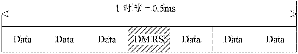
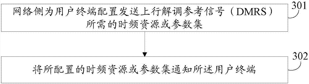
[0156] The base station configures the time-frequency resources required for sending the uplink demodulation reference signal (DMRS) for the user terminal, and indicates to the user terminal, or, the base station and the user terminal predefine the time-frequency resources required for sending the uplink DMRS.

[0157] Among them, the time-frequency resources required for sending uplink DMRS are as follows: Figure 5 As shown, the time-frequency resources include time-domain positions and frequency-domain positions.

[0158] Time domain locations include:

[0159] When the cyclic prefix length of the uplink symbol is the normal length, the time domain position is the 4th time domain symbol of each time slot of the subframe; when the cyclic prefix length of the uplink symbol is the extended length, the time domain position is each The third time domain symbol of the slot;

[0160] Frequency domain locations include:

[0161] The index of the PUSCH bandwidth occupied by the u...

Embodiment 2

[0168] The base station configures the time-frequency resources required for sending the uplink DMRS for the user terminal and indicates to the user terminal, or, the base station and the user terminal predefine the time-frequency resources required for sending the uplink DMRS.

[0169] Among them, the time-frequency resources required for sending uplink DMRS are as follows: Figure 6 As shown, the time-frequency resources include time-domain positions and frequency-domain positions.

[0170] Time domain locations include:

[0171] When the length of the uplink symbol cyclic prefix is ​​the normal length, the time domain position is the second time domain symbol and the sixth time domain symbol of each slot of the subframe; when the uplink symbol cyclic prefix length is the extended length, the time domain position is The position is the second time domain symbol and the fifth time domain symbol of each slot of the subframe;

[0172] Frequency domain locations include:

[0...

Embodiment 3

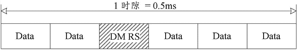
[0179] The base station configures the time-frequency resources required for sending the uplink demodulation reference signal (DMRS) for the user terminal, and indicates to the user terminal, or, the base station and the user terminal predefine the time-frequency resources required for sending the uplink DMRS.

[0180] Among them, the time-frequency resources required for sending uplink DMRS are as follows: Figure 7 As shown, the time-frequency resources include time-domain positions and frequency-domain positions.

[0181] Time domain locations include:

[0182] When the cyclic prefix length of the uplink symbol is the normal length, the time domain position is the 4th time domain symbol of each time slot of the subframe; when the cyclic prefix length of the uplink symbol is the extended length, the time domain position is each The third time domain symbol of the slot;

[0183] Frequency domain locations include:

[0184] All subcarrier positions on the PUSCH bandwidth oc...


PUM


Abstract

The embodiment of the invention discloses an uplink demodulation reference signal configuration method, a network side network element, and an uplink DMRS transmission method and apparatus. The uplink demodulation reference signal configuration method comprises the following steps: the network side configures a time-frequency resource or parameter set necessary for sending an uplink DMRS to a user terminal, and notifies the configured time-frequency resource or parameter set of the user terminal; or the network side and the user terminal pre-define the time-frequency resource or parameter set necessary for sending the uplink DMRS by the user terminal, wherein the time-frequency resource or parameter set comprises a time domain position, a frequency domain position, a virtual cell ID set, a user-specific or resource-specific parameter used for determining an uplink DMRS sequence group serial number, and a user-specific or resource-specific parameter used for determining an uplink DMRS sequence displacement pattern.

Description

technical field [0001] The present invention relates to mobile communication technology, in particular to an uplink demodulation reference signal (DMRS, Demodulation Reference Signal) configuration method, a network side network element, and an uplink DMRS transmission method and device. Background technique [0002] The uplink physical channels of the Long Term Evolution (LTE, Long Term Evolution) system include Physical Random Access Channel (PRACH, Physical Random Access Channel), Physical Shared Channel (PUSCH, Physical uplink shared channel), Physical Uplink Control Channel (PUCCH, Physical Uplink Control Channel). The uplink scheduling information (Uplink Scheduling Information) of the PUSCH is sent by the network side to the target UE through a physical downlink control channel (PDCCH, Physical Downlink Control Channel). The uplink scheduling information includes: resource allocation related to the physical uplink shared channel, modulation and coding scheme, DMRS cy...

Claims


Application Information

Patent Timeline
Patent Type & Authority Applications(China)
IPC IPC(8): H04L5/00H04W72/04
CPCH04L5/0048H04L5/0051H04W72/23H04L5/00H04W72/04
Inventor 王瑜新鲁照华陈艺戬李儒岳李永肖华华吴昊蔡剑兴
Owner ZTE CORP
Why Eureka
Try Eureka