Portal frame special for device installation of urban rail traffic power supply system

A technology of urban rail transit and power supply system, which is applied in the field of installation and construction of urban rail transit power supply system equipment, which can solve problems such as cabinet damage, wall top pollution, and tediousness, so as to improve installation efficiency, reduce safety risks, and facilitate disassembly and transportation Effect

Inactive Publication Date: 2017-08-15
中铁一局集团电务工程有限公司
View PDF2 Cites 6 Cited by
  • Summary
  • Abstract
  • Description
  • Claims
  • Application Information

AI Technical Summary

Problems solved by technology

[0002] At present, one of the traditional equipment installation methods for urban rail transit is to transport the equipment to the basic channel steel with a manual forklift, stabilize the cabinet with a large rope, and then use crowbars and round steel bars to assist the equipment on the basic channel steel and slowly Slowly move to a suitable installation position. This method is time-consuming and labor-intensive. The most important thing is to cause local damage to the cabinet body, especially the contact part between the crowbar and the cabinet body is likely to cause paint peeling and deformation.
Moreover, when the center of gravity of a large cabinet is unstable, it is easy to cause dumping, endangering the safety of operators and equipment
Another common installation method is to install chemical anchor bolts or mechanical anchor bolts on the top of the wall directly above the equipment to be installed, and t

Method used


Image

  • Portal frame special for device installation of urban rail traffic power supply system
  • Portal frame special for device installation of urban rail traffic power supply system

Examples


Embodiment Construction

[0021] The present invention is further described below in conjunction with specific embodiment:

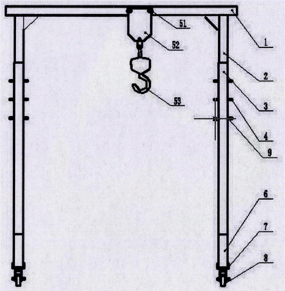
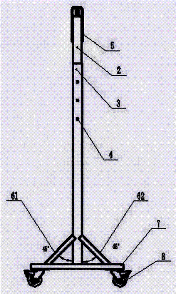
[0022] Such as figure 1 and figure 2 As shown, a gantry dedicated to the installation of urban rail transit power supply system equipment includes a crossbeam 1, which is an H-shaped I-beam, and is respectively connected to the first column 2 on both sides of the crossbeam 1. The bottom of the first column 2 is correspondingly connected with the second column 3, and the first column 2 expands and contracts up and down inside the second column 3, and the bottom of the second column 3 is correspondingly connected with the channel steel 7 of the base. The second column 3 is provided with a plurality of positioning through holes 9, and the positioning through holes 9 are correspondingly connected with the positioning pins 4 passing through the second column 3, and the bottom of the base channel steel 7 corresponds to the universal caster 8 To connect, a moving pulley 5 is provided...


PUM


Abstract

The invention discloses a portal frame special for device installation of an urban rail traffic power supply system. The portal frame comprises cross beams. The cross beams are H-shaped I-steel, the two sides of the cross beams are correspondingly connected with first stand columns correspondingly. The bottoms of the first stand columns are correspondingly connected with second stand columns, and the first stand columns vertically stretch out and draw back in the second stand columns. The bottoms of the second stand columns are correspondingly connected with base steel channels, and a plurality of positioning through holes are formed in the second stand columns and correspondingly connected with positioning pins penetrating through the second stand columns. The bottoms of the base steel channels are correspondingly connected with universal trundles, and movable slide wheels are arranged on the cross beams. The portal frame special for device installation of the urban rail traffic power supply system has the advantages that the height can be adjusted, installation, dismantling and moving are convenient, construction is convenient and fast, and destruction and pollution to structural beams or the wall top are reduced.

Description

technical field [0001] The invention belongs to the field of installation and construction of urban rail transit power supply system equipment, and relates to a gantry dedicated to the installation of urban rail transit power supply system equipment. Background technique [0002] At present, one of the traditional equipment installation methods for urban rail transit is to transport the equipment to the basic channel steel with a manual forklift, stabilize the cabinet with a large rope, and then use crowbars and round steel bars to assist the equipment on the basic channel steel and slowly Slowly move to a suitable installation position. This method is time-consuming and laborious. The most important thing is to cause local damage to the cabinet, especially the part where the crowbar is in contact with the cabinet is likely to cause paint peeling and deformation. Moreover, when the center of gravity of a large cabinet is unstable, it is easy to cause dumping, endangering the...

Claims


Application Information

Patent Timeline
IPC IPC(8): B66C19/00B66C5/04
CPCB66C19/00B66C5/04
Inventor 左传文
Owner 中铁一局集团电务工程有限公司
Why Eureka
Try Eureka