Speed skating boots

A technology for skates and skates, applied to skates, skating parts, sports accessories, etc., can solve problems such as unreliable lubrication effects, achieve the effects of solving uneven ice surfaces, saving usage, and improving lubrication effects

Active Publication Date: 2017-08-18
王茵
View PDF6 Cites 2 Cited by
  • Summary
  • Abstract
  • Description
  • Claims
  • Application Information

AI Technical Summary

Problems solved by technology

[0005] The purpose of the present invention is to solve the problem that the lubrication effect obtained by relying solely on the pressure of the human body is unreliable for the skates of the existing speed skating skates

Method used


Image

  • Speed skating boots
  • Speed skating boots
  • Speed skating boots

Examples


specific Embodiment approach 1

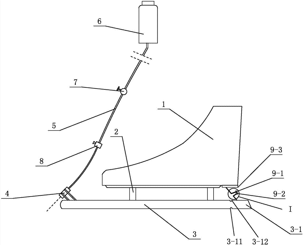
[0009] Specific implementation mode one: combine figure 1 This embodiment will be described. The present embodiment speed skating skate comprises shoe body 1, connecting frame 2 and cutter body 3, and cutter body 3 is fixed on the bottom surface of shoe body 1 by connecting frame 2, and it also includes nozzle 4, connecting pipe 5, water storage tank 6 and Manual switch 7, nozzle 4 is fixed on the upper surface of the front end of cutter body 3, the nozzle of nozzle 4 points to the place 1.5 to 5.5 mm ahead of the front end of cutter body 3, and the water inlet of nozzle 4 is connected to the water storage tank 6 through connecting pipe 5. On the water outlet, the connecting pipe 5 is provided with a manual switch 7 . When the speed skater is skating, the water storage tank 6 is suspended on the waist, and only connected to the shower nozzle 4 by a soft connecting pipe 5 . Shower nozzle 4, connecting pipe 5 and water storage tank 6 all can be selected non-metallic material f...

specific Embodiment approach 2

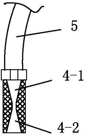
[0010] Specific implementation mode two: combination figure 2 Describe this embodiment, the difference between this embodiment and Embodiment 1 is: the inner cavity of the nozzle 4 is divided into a contraction beam section 4-1 and an expansion beam section 4-2 along its length direction, and the water The fluid flows through the constricted beam section 4-1 and the expanded beam section 4-2 successively, and the constricted beam section 4-1 and the expanded beam section 4-2 are tapered inner holes. With such an arrangement, when the fluid moves in the constricted beam section 4-1, the fluid is continuously accelerated according to the principle that the flow velocity is small at a large cross-section and high at a small cross-section. When reaching the narrow throat, the flow velocity reaches a certain scale. After crossing the narrow throat, it is just according to the principle that the larger the cross-section, the faster the flow velocity, so it can be sprayed at a high...

specific Embodiment approach 3

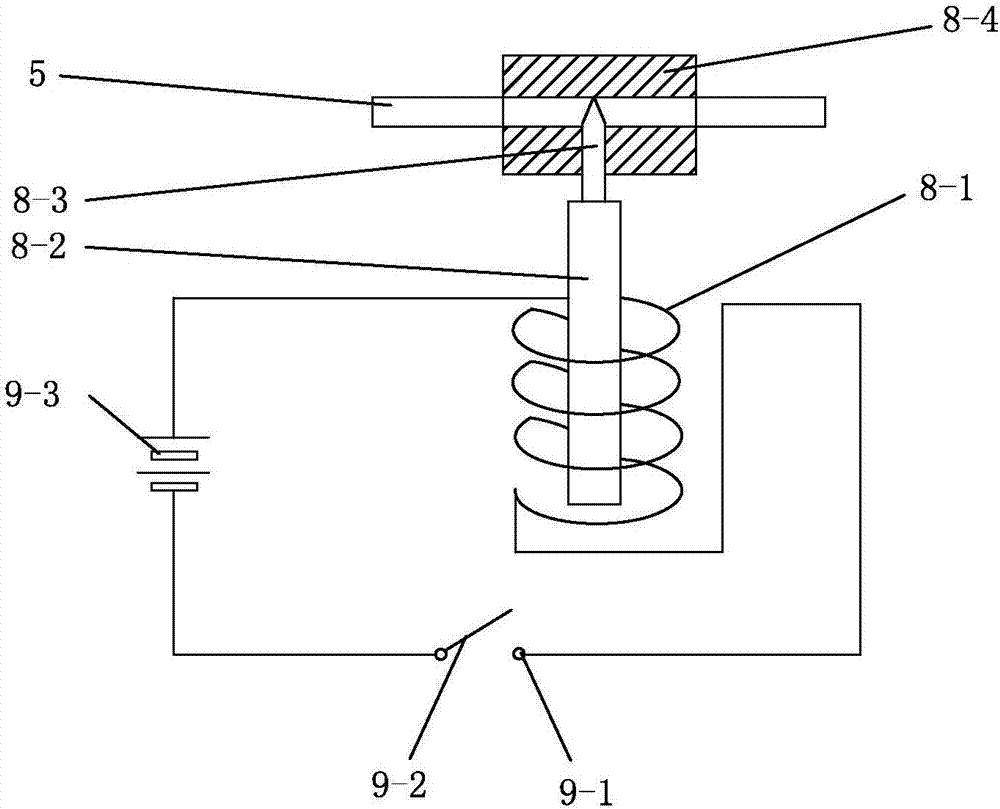
[0012] Specific implementation mode three: combination figure 1 , image 3 and Figure 4 Describe this embodiment. The difference between this embodiment and Embodiment 1 is that it also includes an electromagnetic pipeline valve 8 and a control circuit. The electromagnetic pipeline valve 8 is composed of an electromagnetic coil 8-1, an armature 8-2, a valve core 8- 3 and valve body 8-4, the control circuit is composed of static contact 9-1, moving contact 9-2 and battery 9-3, and the electromagnetic pipeline valve 8 is set on the connecting pipe 5 to control the flow of water The spool 8-3 is set in the valve body 8-4, the front end of the armature 8-2 is fixed with the spool 8-3, the rear end of the armature 8-2 is set in the electromagnetic coil 8-1, and the battery 9- The positive pole of 3 connects one end of electromagnetic coil 8-1, and the other end of electromagnetic coil 8-1 connects static contact 9-1, and movable contact 9-2 connects the negative pole of battery ...


PUM


Abstract

The invention relates to a pair of speed skating boots, and belongs to the field of sports instruments. The pair of speed skating boots solves the problem that ice skate blades of existing speed skating boots are unreliable in lubricating effect obtained purely in virtue of human body pressure intensity. Each speed skating boot comprises a boot body, a connecting rack and a blade body; the blade body is fixedly onto the bottom surface of the boot body through the connecting rack. Each speed skating boot also comprises a spray head, a connecting pipe, a water storage tank and a hand switch; the spray head is fixed at the position of the upper surface of the front end of the blade body; a spray nozzle of the spray head faces the front part of the front end of the blade body; a water inlet of the spray head is connected onto a water outlet of the water storage tank through the connecting pipe; and the hand switch is arranged on the connecting pipe. During ice skating of a speed skating person, water is sprayed by the spray head in front of the blade bodies, a water film is formed on an ice surface, and the friction force between the blade bodies and the ice surface is reduced, so that the skating speed can be increased. Due to the fact that the sprayed water cannot be frozen instantly, the problem that a stable water lubricating effect cannot be formed by the human body pressure intensity after the temperature is reduced is solved.

Description

technical field [0001] The invention relates to a speed skating skate, which belongs to the field of sports equipment. Background technique [0002] The skates of existing ice skating mainly contain three kinds: speed skating skates, figure skates, ice hockey skates. Ice sports are inseparable from skates, and the key to skates is the pair of sharp skates. For speed skating skates, its most important parameter is the gliding speed, and reducing the friction between the skate and the ice surface is an important factor for improving the skating speed. [0003] The generally accepted theory is that when a skater is skating, the contact between the ice blade and the ice surface is under great pressure, which lowers the melting point of the ice, and the ice under the blade melts into water, and the thin layer of water that melts is equivalent to a lubricant. Thereby reducing the frictional force between the ice blade and the ice surface and increasing the skating speed. [000...

Claims


Application Information

Patent Timeline
Patent Type & Authority Applications(China)
IPC IPC(8): A63C1/00A63C1/30
CPCA63C1/00A63C1/30
Inventor 王茵
Owner 王茵
Why Eureka
Try Eureka