Gas-liquid multistage separation device for gas bearing experiment for incoming flow of pump

A multi-stage separation and gas-liquid separation plate technology, applied in the field of pump experiments, can solve the problems of unfavorable floor space, single separator, bulky volume, etc., and achieve the effect of compact structure, high separation efficiency and sufficient separation

Active Publication Date: 2017-08-18
ZHEJIANG SCI-TECH UNIV
View PDF3 Cites 2 Cited by
  • Summary
  • Abstract
  • Description
  • Claims
  • Application Information

AI Technical Summary

Problems solved by technology

In terms of the gas-liquid mixed fluid where the separation fluid is the main one, the commonly used separator is relatively simple.
Most of the existing gas-liquid separation devices use only gravity separation, let the fluid velocity drop first and then separate, the separation efficiency is not very ideal, and the volume is huge, which is not conducive to the laboratory with a small footprint

Method used


Image

  • Gas-liquid multistage separation device for gas bearing experiment for incoming flow of pump
  • Gas-liquid multistage separation device for gas bearing experiment for incoming flow of pump
  • Gas-liquid multistage separation device for gas bearing experiment for incoming flow of pump

Examples


Embodiment Construction

[0030] The specific embodiments of the present invention will be further described below in conjunction with the accompanying drawings.

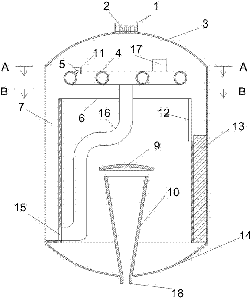
[0031] Such as figure 1 As shown, the specific implementation of the present invention includes a tank body 14 and a first-level separation part placed in the tank body 14, a second-level separation part and a third-level separation part, and the first-level separation part is placed in the inner cavity of the tank body 14 In the upper space, the second-level separation part is placed on the inner wall of the tank body 14, the first-level separation part and the second-level separation part are connected by a water pipe 16, the third-level separation part is placed at the bottom of the tank body 14, and the tank body 14 The tank cover 3 has a top air outlet 1, and a wire mesh filter 2 is installed at the top air outlet 1.

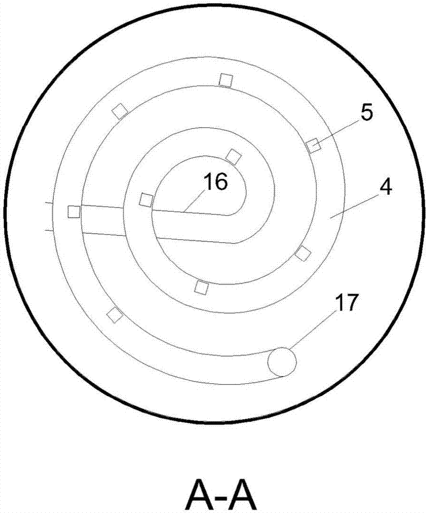
[0032] Such as figure 2 As shown, the first-stage separation part is mainly composed of a spiral tube 4, a nozzle 5 ...


PUM


Abstract

The invention discloses a gas-liquid multistage separation device for a gas bearing experiment for incoming flow of a pump. The gas-liquid multistage separation device comprises a tank as well as a first-stage separation part, a second-stage separation part and a third-stage separation part which are arranged in the tank, wherein the first-stage separation part is arranged in upper space of an inner chamber of the tank, the second-stage separation part is arranged on the peripheral surface of the inner wall of the tank and connected with the first-stage separation part through a water pipe, and the third-stage separation part is arranged at the bottom of the tank; the first-stage separation part comprises a spiral pipe, spray nozzles and baffle plates; the second-stage separation part comprises an annular chamber, inlet baffle plates, gas-liquid separation plates and an outlet baffle plate; the third-stage separation part comprises a liquid separation plate and a conical diversion pipe which is big end up. The gas-liquid multistage separation device adopts compact mechanism, is high in separation efficiency and can effectively solve the problem about fluid degassing in experiments and engineering.

Description

technical field [0001] The invention relates to the field of pump experiments and the technical fields of chemical machinery, in particular to a gas-liquid multi-stage separation device for gas-containing experiments in pump flow. In addition to meeting the separation of water-insoluble gases in water, it can also meet the separation of fluid-insoluble gases in other fluids. Background technique [0002] In enterprises or laboratories, the experimental medium used in pump test benches is generally water, and it is recycled. It is sucked into the pump by the water storage tank, and then discharged into the water storage tank at the outlet of the pump. The experimental gas filling device for the incoming flow containing gas is generally located in the inlet pipe between the pump and the storage tank. However, to ensure that the gas phase content percentage at the pump inlet is completely controlled by the gas filling device, it is necessary to ensure that the water in the wa...

Claims


Application Information

Patent Timeline
Patent Type & Authority Applications(China)
IPC IPC(8): B01D19/00
CPCB01D19/0052B01D19/0068
Inventor 朱祖超蔡明哲崔宝玲
Owner ZHEJIANG SCI-TECH UNIV
Why Eureka
Try Eureka