Device for processing apparatus, particularly for laser processing apparatus, and laser processing apparatus

A technology of laser processing and processing equipment, which is applied to the device in the preamble and the field of laser processing equipment, and can solve the problems of inability to suck away particles or emissions

Inactive Publication Date: 2017-08-18
ROBERT BOSCH GMBH
View PDF10 Cites 2 Cited by
  • Summary
  • Abstract
  • Description
  • Claims
  • Application Information

AI Technical Summary

Problems solved by technology

However, no statements about possible suction of particles or emissions can be obtained from the mentioned documents

Method used


Image

  • Device for processing apparatus, particularly for laser processing apparatus, and laser processing apparatus
  • Device for processing apparatus, particularly for laser processing apparatus, and laser processing apparatus

Examples


Embodiment Construction

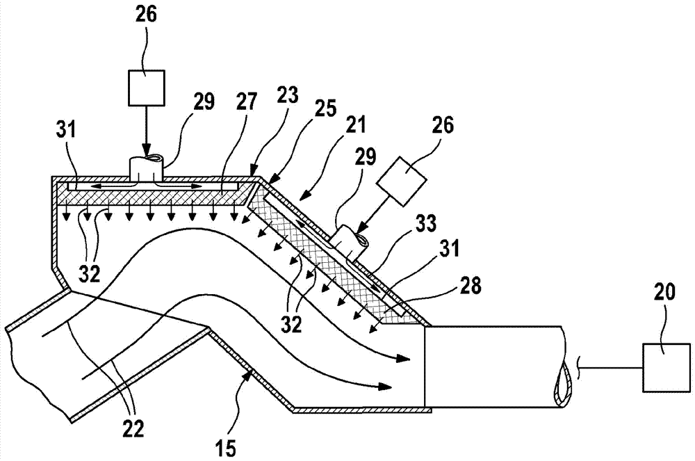
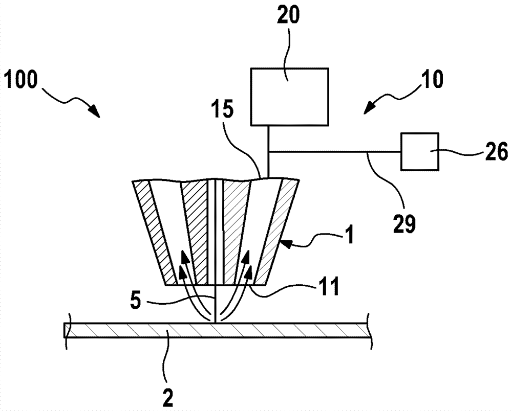
[0020] exist figure 1 A treatment head 1 of a treatment device designed as a laser treatment device 100 is shown in a strongly simplified manner in FIG. The laser processing device 100 is used, for example, for the separation or shearing of a workpiece 2 which is formed, for example, in the form of a sheet. For this purpose, a laser beam 5 emerges from the treatment head 1 of the laser treatment system 100 , which is guided by an optical system (not shown) and which strikes, for example, perpendicularly to the surface of the workpiece 2 . When the laser beam 5 hits the workpiece surface, the material of the workpiece 2 is melted or evaporated. The vaporized material of the workpiece 2 is a particle-containing emission. In order that these emissions or particles do not settle on the workpiece surface 2 , the laser processing device 100 also has a device 10 for suctioning the emissions or particles from the region of the workpiece 2 .

[0021] The device 10 has, for example, ...


PUM


Abstract

The invention relates to a device (10) for sucking away the discharge during processing for a processing apparatus, particularly for a laser processing apparatus. The device includes a pump channel (15) for guiding the discharge, wherein the pump channel (15) is effectively connected with a tool (20) capable of generating low pressure. The at least one sectional part (21) of the pump channel (15) is arranged in the effective connection with a mechanism (25) for generating overpressure, and the mechanism (25) applies a pneumatic overpressure to the flow cross-section of the pump channel (15).

Description

technical field [0001] The invention relates to an arrangement according to the preamble of claim 1 for a treatment plant, in particular a laser treatment plant. Furthermore, the invention relates to a laser treatment installation with a device according to the invention. Background technique [0002] DE 10 2009 038 650 B4 discloses a device for sucking up emissions during laser treatment for a treatment facility designed as a laser treatment facility according to the preamble of claim 1 . The known device is characterized in that particle-containing emissions generated in the region of the workpiece during the laser treatment, for example by evaporating material of the workpiece, are sucked away by means of a suction device. The mentioned documents are concerned with the contamination of the interior of the suction device by emissions or particles and suggest a constructive design of the suction device or its housing which achieves a A relatively easy cleanability. In ot...

Claims


Application Information

Patent Timeline
Patent Type & Authority Applications(China)
IPC IPC(8): B23K26/16
CPCB23K26/16B23K26/38B23K26/1462
Inventor T.格哈特
Owner ROBERT BOSCH GMBH
Why Eureka
Try Eureka