A rivet direct vibration feeding mechanism

A feeding mechanism and rivet technology, applied in the direction of vibrating conveyors, conveyors, conveyor objects, etc., can solve the problems of automatic queuing and feeding, low efficiency, etc., achieve high queuing efficiency and meet the effect of high-efficiency automation

Active Publication Date: 2019-05-10
海宁艺通工艺品有限公司
View PDF5 Cites 0 Cited by
  • Summary
  • Abstract
  • Description
  • Claims
  • Application Information

AI Technical Summary

Problems solved by technology

[0002] The rivet is a commonly used part in the production and assembly process. In the automatic production, the rivet needs to be fed according to the set posture. The existing rivet automatic feeding mechanism generally uses the center of gravity of the rivet to deviate from the geometric center to perform automatic queuing. Rivets with incorrect postures are returned to the barrel, which has low efficiency, and this type of automatic rivet feeding mechanism cannot automatically queue up and feed rivets with a similar center of gravity and geometric center (such as rivets with a large outer diameter in the middle section and small outer diameters at both ends). For this reason, the present invention provides a rivet direct vibration automatic feeding mechanism that does not rely on the center of gravity of the rivet for automatic feeding

Method used


Image

  • A rivet direct vibration feeding mechanism
  • A rivet direct vibration feeding mechanism

Examples


Embodiment Construction

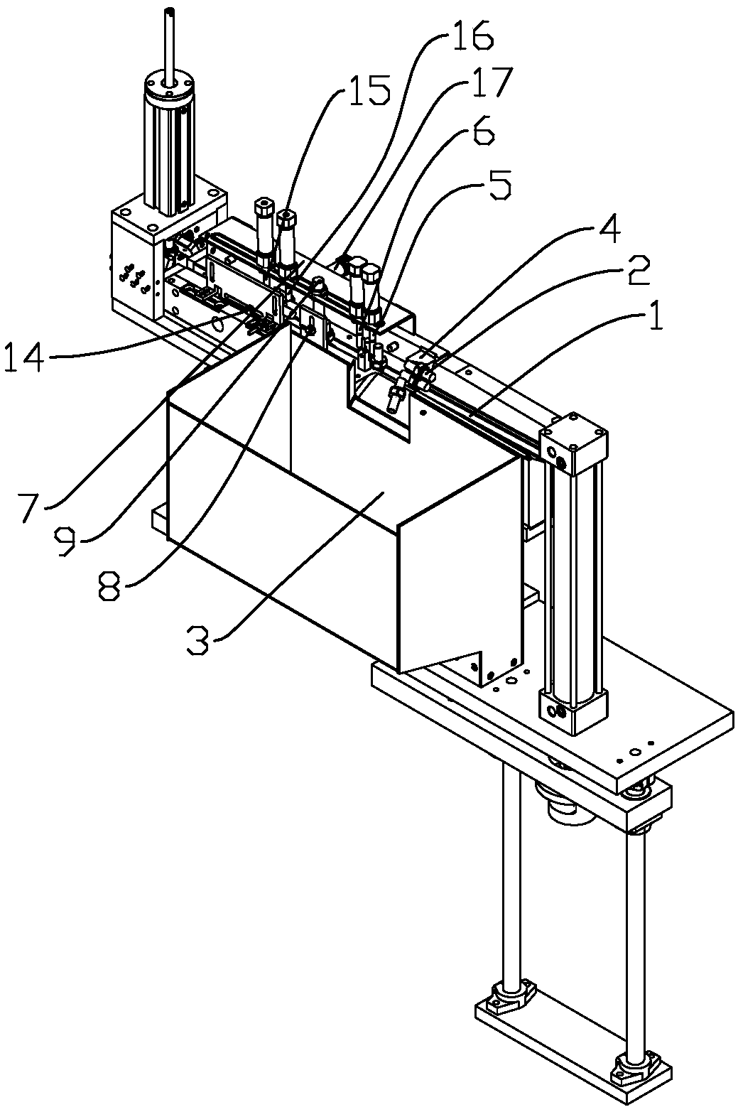
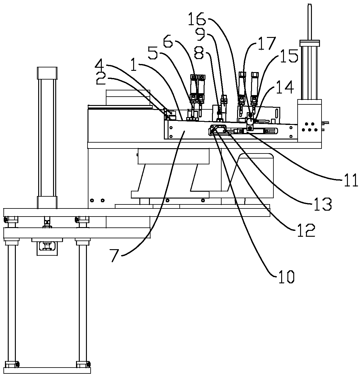
[0025] refer to Figure 1 ~ Figure 2 , the present invention is a rivet direct vibration feeding mechanism, comprising:

[0026] The conveying device 1 is used to carry the rivet 2 and move the rivet 2 forward;

[0027] The material selection device acts on the rivets 2 on the conveying device 1, and is used to remove overlapping rivets 2;

[0028] The position adjustment device is located behind the material selection device along the conveying direction of the rivet 2, and is used to adjust the rivet 2 in the wrong posture to the correct posture;

[0029] The material barrel 3 is docked with the conveying device 1, and is used for providing the rivets 2 to be placed on the conveying device 1, and receiving the rivets 2 rejected by the material selection device.

[0030] The rivet 2 on the conveying device 1 has four postures, which are upright posture, inverted posture, forward flat posture, and backward flat posture. In the flat posture, two rivets 2 may be superimposed o...


PUM


Abstract

The invention discloses a linear vibration feeding mechanism for rivets. The linear vibration feeding mechanism comprises a conveying device, a sorting device and an aligning device. The conveying device is used for bearing the rivets and further moving the rivets forward. The sorting device acts on the rivets on the conveying device and used for removing the overlapped rivets. The aligning device is located behind the sorting device in the rivet conveying direction and used for adjusting the rivets at the wrong posture into the correct posture. The rivets on the conveying device have four postures including the erected posture, the inverted posture, the forward horizontal placing posture and the backward horizontal placing posture. When the rivets are at the horizontal placing posture, the phenomenon that two rivets are overlaid together is likely to happen. The overlaid rivets are removed through the sorting device. The rivets at the inverted posture, the forward horizontal placing posture and the backward horizontal placing posture can be adjusted to be at the erected posture through the aligning device, and thus the purpose of ordered arrangement is achieved. In the whole link, only the sorting device can remove the rivets, no rivets can be removed in the other links, and therefore the queuing efficiency is high and the requirements of high-efficiency and automation can be met.

Description

technical field [0001] The invention relates to the field of automatic feeding, in particular to a rivet direct vibration feeding mechanism. Background technique [0002] The rivet is a commonly used part in the production and assembly process. In the automatic production, the rivet needs to be fed according to the set posture. The existing rivet automatic feeding mechanism generally uses the center of gravity of the rivet to deviate from the geometric center to perform automatic queuing. Rivets with incorrect postures are returned to the barrel, which has low efficiency, and this type of automatic rivet feeding mechanism cannot automatically queue up and feed rivets with a similar center of gravity and geometric center (such as rivets with a large outer diameter in the middle section and small outer diameters at both ends). For this reason, the present invention provides a rivet direct-vibration automatic feeding mechanism for automatic feeding without the center of gravity...

Claims


Application Information

Patent Timeline
Patent Type & Authority Patents(China)
IPC IPC(8): B65G47/256B65G27/04
CPCB65G27/04B65G47/256
Inventor 黎德智
Owner 海宁艺通工艺品有限公司
Why Eureka
Try Eureka