Hydraulic lifting machine

A lift and hydraulic technology, which is applied in the field of lifts, can solve the problems of small lifting range, insufficient connection, poor stability, etc., and achieve the effect of increasing the lifting range, increasing the service life, and increasing the lifting stability

Inactive Publication Date: 2017-08-18
YANCHENG DONGFANG TIANCHENG MACHINERY
View PDF0 Cites 1 Cited by
  • Summary
  • Abstract
  • Description
  • Claims
  • Application Information

AI Technical Summary

Problems solved by technology

[0004] The purpose of the present invention is to provide a hydraulic lift to solve the pr

Method used


Image

  • Hydraulic lifting machine
  • Hydraulic lifting machine

Examples


Embodiment Construction

[0013] The following will clearly and completely describe the technical solutions in the embodiments of the present invention with reference to the accompanying drawings in the embodiments of the present invention. Obviously, the described embodiments are only some, not all, embodiments of the present invention. Based on the embodiments of the present invention, all other embodiments obtained by persons of ordinary skill in the art without making creative efforts belong to the protection scope of the present invention.

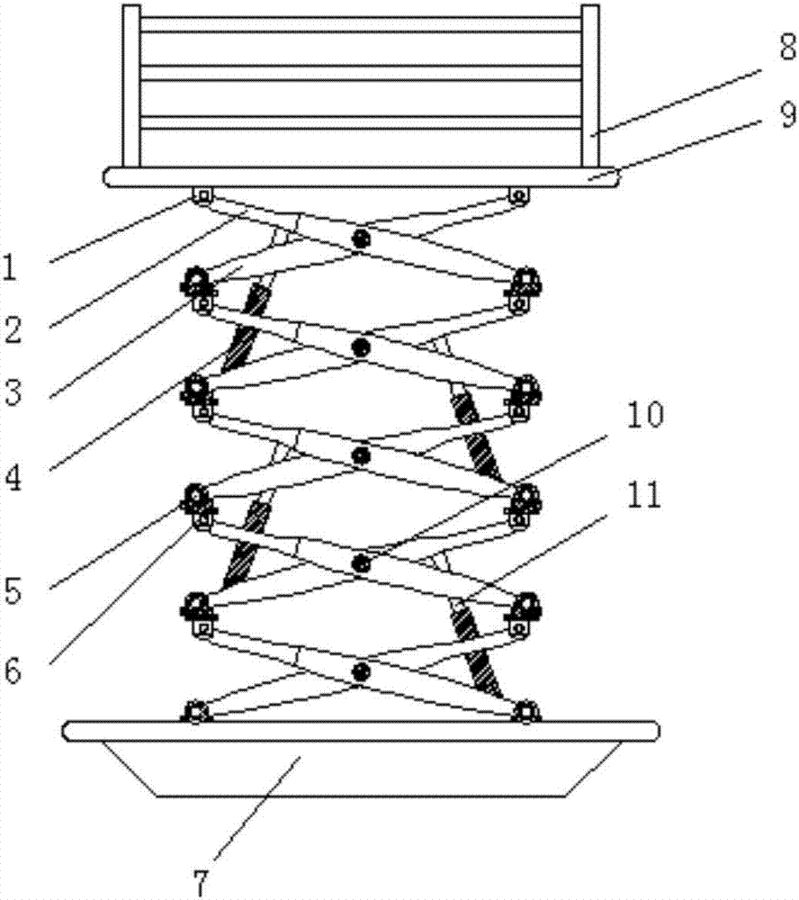
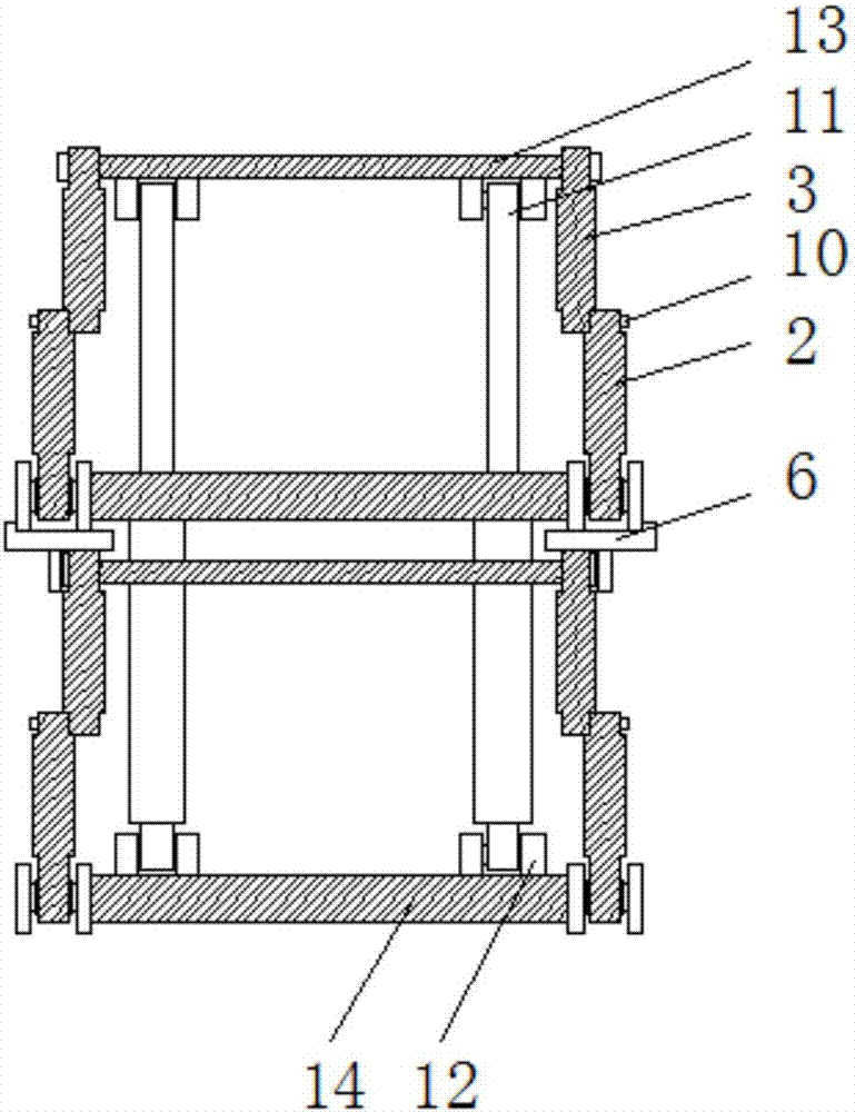
[0014] see Figure 1~2 , in an embodiment of the present invention, a hydraulic lift includes a base 7, an outer support 2 and an inner support 3 are installed above the base 7, the outer support 2 and the inner support 3 are used to support the pallet 9, the outer support 2 and the The intersection position between the inner brackets 3 is connected by hinge 10, and the hinge 10 can make the outer bracket 2 and the inner bracket 3 rotate mutually, and one end ...


PUM


Abstract

The invention discloses a hydraulic lifting machine, comprising a base; outer supports and inner supports are mounted above the base, crossed positions between the outer supports and the inner supports are rotatably connected by hinges, one ends of the outer supports and the inner supports are mounted on second fixing plates, first fixing plates are mounted on the two ends of first fixing rods, two sides of each first fixing rod and the corresponding second fixing rod are respectively provided with a first hydraulic device and a second hydraulic device by a third fixing plate, a carrier plate is mounted on the tops of the outer supports and the inner supports, and a protective guard is mounted above the carrier plate. Ten pairs of lifting devices combined by the outer support and the inner support are respectively mounted on the two sides above the base, such that a lifting amplitude of the lifting machine is greatly increased, each pair of inner support and outer support is welded and connected by a welding block, and through such connecting manner, jointing firmness is increased.

Description

technical field [0001] The invention relates to the field of lifts, in particular to a hydraulic lift. Background technique [0002] The elevator is a kind of elevator equipment composed of traveling mechanism, hydraulic mechanism, electric control mechanism and supporting mechanism. The hydraulic oil is under a certain pressure formed by the vane pump, and enters the lower end of the hydraulic cylinder through the oil filter, explosion-proof electromagnetic reversing valve, throttle valve, hydraulic control check valve, and balance valve, so that the piston of the hydraulic cylinder moves upward to lift the weight. The oil returned from the upper end of the hydraulic cylinder returns to the oil tank through the explosion-proof electromagnetic reversing valve, and its rated pressure is adjusted through the overflow valve, and the reading value of the pressure gauge is observed through the pressure gauge, which is determined by the platform and the equipment, motor, An integ...

Claims


Application Information

Patent Timeline
IPC IPC(8): B66F7/08
CPCB66F7/0666B66F7/08
Inventor 邢礼宏
Owner YANCHENG DONGFANG TIANCHENG MACHINERY
Why Eureka
Try Eureka