Reset mechanism of lock cylinder fixed type cross-shaped mechanical anti-theft lock

A technology of mechanical anti-theft lock and reset mechanism, which is applied in building locks, building structures, buildings, etc. It can solve the problems of low processing precision, big troubles, and the rejection of users, and achieve the effect of low cost and high cost

Active Publication Date: 2017-08-18
BEIHUA UNIV
View PDF10 Cites 9 Cited by
  • Summary
  • Abstract
  • Description
  • Claims
  • Application Information

AI Technical Summary

Problems solved by technology

However, through the test and use of the first batch of products, problems were also found: for some products, when the lock is opened, the cam mechanism is rotated in the opposite direction, or the handle is pressed down without the key inserted, and the cam mechanism is rotated in the opposite direction, the inside and outside The rotating ring failed to reset automatically under the action of the reset tension spring. The reasons are: ①The pinholes of the lock cylinder, the inner rotating ring and the outer rotating ring have poor concentricity and are not smooth. Forcibly driving the inner and outer rotating rings to rotate will cause the lock The axial series movement between the core, the inner rotating ring and the outer rotating ring will increase the contact pressure with the anti-skid plate and the back plate, and the rotation resistance will increase, so it cannot be automatically reset; ② Remove the stepped shaft at both ends of the lock cylinder , The length of the middle part behind the flat shaft is not greater than the design size of the inner and outer rotating rings, so that there is no gap between the inner and outer rotating rings, the anti-skid plate and the back plate, and the contact pressure and rotation resistance increase. It cannot be reset automatically; ③Due to the insufficient size of the coaming, the distance between the anti-skid plate and the back plate becomes smaller, forming pressure on the inner and outer rotating rings, and the inner and outer rotating rings cannot be automatically reset; ④The iron filings and other granular substances are mixed in the Between the lock cylinder, the inner rotating ring, the outer rotating ring, the anti-skid plate and the back plate, the inner and outer rotating rings cannot be reset automatically
In fact, the main reason why the inner and outer rotating rings cannot be automatically reset is that the machining accuracy is too low
[0004] Under normal circumstances, the above-mentioned situation will not occur if the processing error is within the allowable range. However, once the inner and outer rotating rings of individual products cannot be automatically reset for some reason, the key will not be able to be inserted, and the user will be turned away. ; or the key cannot be drawn out, and the anti-theft door cannot be locked, that is, "small problems" cause "big trouble", which cannot ensure that users can rest easy

Method used


Image

  • Reset mechanism of lock cylinder fixed type cross-shaped mechanical anti-theft lock
  • Reset mechanism of lock cylinder fixed type cross-shaped mechanical anti-theft lock
  • Reset mechanism of lock cylinder fixed type cross-shaped mechanical anti-theft lock

Examples


Embodiment approach 1

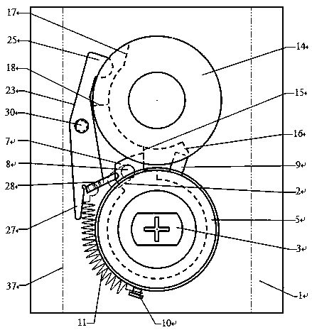
[0051] Implementation mode one: if figure 1 , 2 , 3, 4, 6, 7, 8, 9, 19, and 24, in the lock body of the lock cylinder fixed cross mechanical anti-theft lock, the cam mechanism and the lock cylinder group are installed between the anti-skid plate and the back plate 1 Among them, the cam mechanism includes a camshaft 13, a driven ring 14, an upper flange 15 and a lower flange 16 are arranged on the inner side of the inner side of the driven ring 14, and the driven ring 14 passes through the back plate 1. The part of the shaft hole includes a flat shaft part 21 and a round shaft part 22 at the end. The flat shaft part 21 is fixedly assembled with the main drive disc of the unlocking transmission mechanism and rotates synchronously. The round shaft part 22 is movably assembled with the swing rod. Core 3, inner rotating ring 4, outer rotating ring 5, dialing ring 6, locking post 9, return tension spring connecting post 10 and marble group, lock core 3 is fixed, dialing ring 6 and ...

Embodiment approach 2

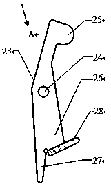
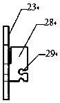
[0056] Implementation mode two: if Figure 5 , 11 , 12, 13, and 14 show that the reset lever 23 is cancelled, and the height of the outside of the reset push edge 18 is increased, that is, the push edge boss 20 is added, so that the push edge boss 20 can "reach enough" when the driven ring 14 reversely rotates “According to” locking column 9 and then promote its reset operation. The height of the flange boss 20 should be less than the gap between the driven ring and the outer rotating ring. Such as Figure 5 , 25 , Shown in 26, the upper end face of locking post 9 is slope shape, and purpose is to make the thrust of pushing edge boss can form the rotational moment to locking post 9 and outer rotating ring 5 reset operation.

[0057] exist Figure 5 Among them, the lock cylinder group and the cam mechanism are arranged horizontally, and the lock hole is located on the left side of the handle (that is, it corresponds to the right-hand door, and if it is on the right side, i...


PUM


Abstract

The invention discloses a reset mechanism of a lock cylinder fixed type cross-shaped mechanical anti-theft lock, and relates to the field of mechanical anti-theft locks. The reset mechanism is mainly characterized in that an original patent technology is improved, namely, a reset lever capable of swinging in two directions is added, an inclined pushing surface which is inclined backwards is arranged on the corresponding position, opposite to an upper flange, of a driven ring, a reset push flange is arranged on the corresponding position, opposite to a lower flange, of the driven ring, when a handle and a cam mechanism are reversely rotated, if an inner rotating ring and an outer rotating ring fail to be automatically reset, the reset lever and the reset push flange sequentially push the inner rotating ring and the outer rotating ring to complete the whole resetting process, and therefore a key can be ensured to be inserted into the lock or pulled out from the lock under any conditions, and the occurrence of a big trouble can be avoided; or the reset lever is not arranged, a push flange boss is additionally arranged on the outer side of the reset push flange, the end part of a locking column is changed into a slope shape, and the same effect can also be realized. According to the reset mechanism, by means of the improvement, added parts are few, the manufacturing cost is low, the various performances of the lock are not affected at all, and users can be ensured to have nothing to worry about at all.

Description

technical field [0001] The invention relates to the field of mechanical anti-theft locks, in particular to a resetting mechanism of a cross-type mechanical anti-theft lock with a fixed lock cylinder. Background technique [0002] In the prior art, the lock cylinder fixed cross mechanical anti-theft lock (patent number ZL201410020215.X), a double-insert anti-theft door (application number 201610068454.1), a double-insert anti-theft door and an external locking device (application number 201610129609.8) , a lock cylinder fixed cross mechanical anti-theft lock matching with a fingerprint lock (application number 201610990489.0), a cam mechanism of a fingerprint lock (application number 201611045195.7), a digital code, a single key combination kit (application number 201610067763.7) and a The profiling device of the key matching machine (application number 201610068057.4) has seven invention patents, all of which have special structures and performances. Among them, the first pa...

Claims


Application Information

Patent Timeline
Patent Type & Authority Applications(China)
IPC IPC(8): E05B15/00E05B15/04
CPCE05B15/0013E05B15/04
Inventor 吕雪寒叶延亮曹俊标周振雄
Owner BEIHUA UNIV
Why Eureka
Try Eureka