A rotating ring forced reset device for an anti-theft lock

A technology of a reset device and a rotating ring, applied in the field of anti-theft locks, can solve problems such as increased cost, and achieve the effects of enhanced reliability, reduced manufacturing cost, and no impact on reliability

Active Publication Date: 2018-05-29
BEIHUA UNIV
View PDF8 Cites 0 Cited by
  • Summary
  • Abstract
  • Description
  • Claims
  • Application Information

AI Technical Summary

Problems solved by technology

If high-quality wear-resistant materials are used, the cost will increase, and it cannot be used as a preferred solution

Method used


Image

  • A rotating ring forced reset device for an anti-theft lock
  • A rotating ring forced reset device for an anti-theft lock
  • A rotating ring forced reset device for an anti-theft lock

Examples


Embodiment Construction

[0034] Combine below Figure 1 to Figure 16 The present invention is further described.

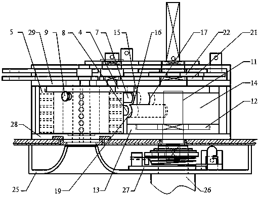
[0035] Such as figure 1 As shown, in the anti-theft lock body corresponding to the device of the present invention, the lock cylinder group and the cam mechanism are installed between the anti-skid plate 28 and the back plate 29 .

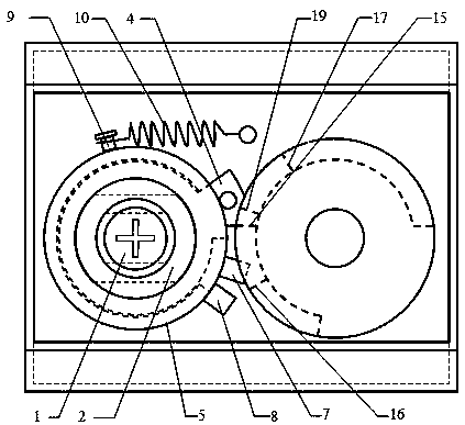
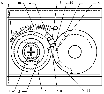
[0036] Such as figure 1 , 2 with Figure 12-16 As shown, the lock cylinder group includes a lock cylinder 1, an inner rotating ring 2, an outer rotating ring 5, a dial ring 3, a locking column 7, a reset column 8, a reset tension spring connecting column 9 and a marble group, and the lock cylinder 1 is fixed , the periphery of the lock core 1 is successively an inner rotating ring 2 and an outer rotating ring 5, and the dial ring 3 is assembled with the inside end of the inner rotating ring 2 and rotates synchronously. One side of the dial ring 3 is provided with a dial ring protruding end 4. The protruding end 4 of the dialing ring is located in the gap ...


PUM


Abstract

The invention provides a device for forcedly resetting a rotation ring of a burglar-proof lock and relates to the field of burglar-proof locks. The device is mainly characterized in that a resetting pillar is additionally arranged on an outer rotation ring of the lock; a third flange and a resetting pillar channel are additionally arranged in corresponding positions on a driven ring of a cam; when the rotation ring is incapable of automatically resetting, a lever handle is reversely rotated and the resetting pillar and a locking pillar are successively pushed to operate by using a resetting and pushing flange on the original driven ring and the locking pillar on the outer rotation ring, so that the forced resetting process of the rotation ring is completed. The device is capable of ensuring that a key can be inserted into the lock or withdrawn from the lock in any case; the device is free of space occupation and free of influence on overall layout; meanwhile, the contact between the additionally-arranged parts and the contact between the additionally-arranged parts and the original parts can be avoided in the daily operation process of automatic resetting of the rotation ring, so that the phenomenon of abrasion can be avoided.

Description

technical field [0001] The invention relates to the field of anti-theft locks, in particular to a forced reset device for a rotating ring of an anti-theft lock. Background technique [0002] In the prior art, "lock core fixed cross mechanical anti-theft lock" (patent No. ZL201410020215.X), "a double-insert anti-theft door" (patent No. ZL201610068454.1), "double-insert anti-theft door and external lock Closing device" (Patent No. ZL201610129609.8), "A digital code, single key combination kit" (Patent No. ZL201610067763.7), "A profiling device for key matching machine" (Patent No. ZL201610068057.4), "Cylinder fixed cross mechanical anti-theft lock matching with fingerprint lock" (application number 201610990489.0), "a cam mechanism for fingerprint lock" (application number 201611045195.7) and "resetting mechanism for lock cylinder fixed cross mechanical anti-theft lock" ( Application No. 201710193748.1) and other eight invention patent applications, all of which have special ...

Claims


Application Information

Patent Timeline
IPC IPC(8): E05B15/00E05B3/00
CPCE05B3/00E05B15/00E05B15/0013
Inventor 吕雪寒
Owner BEIHUA UNIV
Why Eureka
Try Eureka