
Hydroscillator

A hydraulic oscillator and oscillator technology, which is applied in the direction of drilling with vibration, vibration generating device, wellbore/well parts, etc. problems, to achieve the effect of saving non-renewable energy, improving the internal working environment, and improving the inability to lift

Inactive Publication Date: 2017-08-18
惠天昱
View PDF0 Cites 0 Cited by
  • Summary
  • Abstract
  • Description
  • Claims
  • Application Information

AI Technical Summary

Problems solved by technology

[0002] In the process of the continuous expansion of urbanization scale and the continuous improvement of the degree of industrialization in my country, the proportion of industrial production continues to increase, and the role of hydraulic oscillators is particularly important. The existing hydraulic oscillators have complex structures and single functions. There will be a lot of problems that are difficult to solve. The original invention cannot be cleaned frequently because the interior is complex and closed. Renewable energy, in the original invention, in the cold winter, some internal equipment would freeze, making it impossible to work. In the hot summer, the internal working temperature was too high, so the work could not be carried out normally. The original invention could not adjust the height, so that The staff can't adjust to a suitable position, which affects the work efficiency of the staff, so a hydraulic oscillator is urgently needed to solve the above-mentioned problems

Method used


Image

  • Hydroscillator
  • Hydroscillator
  • Hydroscillator

Examples


specific Embodiment approach

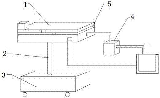
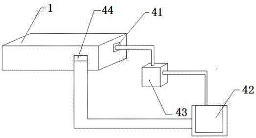
[0025] The specific embodiment: the staff first inserts the water pipe into the pool 42, the water pump 43 and the pool 42 are connected by the water pipe, the staff starts the water pump 43, the water pump 43 works, the water pump 43 introduces the water in the pool 42 into the water inlet 41 through the water pipe, and the water Enter the oscillator from the water inlet 41 for cleaning. After the cleaning is completed, the water flows out from the water outlet 44, and the flowing water flows back to the pool 42 through the water pipe to realize the recycling of water resources. This design solves the disadvantages of the original hydraulic oscillator that is difficult to clean. The present invention can be cleaned more comprehensively and thoroughly, and water can be recycled, so a large amount of non-renewable energy is saved, and the effect of increasing the convenience of cleaning the present invention is achieved.

[0026] In the hot summer, the staff starts the switch 2 ...


PUM


Abstract

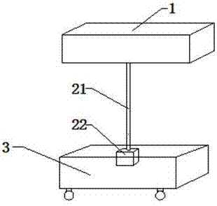
The invention provides a hydraulic oscillator, which includes a water inlet, a water pool, a water pump, a water outlet, a straight rod, a motor, an electric fan, a switch one, a switch two, a heating plate and a cooling plate. Installed on the right side of the water pump, the water pump and the pool are connected through water pipes, there is a water inlet on the right end of the oscillator, the water inlet is connected to the water pump through a water pipe, and there is a water outlet on the front face of the oscillator, and the water outlet is connected to the pool through a water pipe , the straight rod is assembled on the lower end of the oscillator, the motor is installed at the lower end of the straight rod, the motor is assembled in the base, the heating plate and the cooling plate are installed in the oscillator, the heating plate is installed on the lower end of the cooling plate, and the electric fan is installed on the In the cooling plate, the first switch is installed on the right end surface of the heating plate, and the second switch is assembled on the right end surface of the cooling plate. The invention can save non-renewable energy, improve the disadvantage that the oscillator cannot be raised and lowered, and has a wide application range and strong reliability.

Description

technical field [0001] The invention is a hydraulic oscillator, which belongs to the field of auxiliary tools. Background technique [0002] In the process of the continuous expansion of urbanization scale and the continuous improvement of the degree of industrialization in my country, the proportion of industrial production continues to increase, and the role of hydraulic oscillators is particularly important. The existing hydraulic oscillators have complex structures and single functions. There will be a lot of problems that are difficult to solve. The original invention cannot be cleaned frequently because the interior is complex and closed. Renewable energy, in the original invention, in the cold winter, some internal equipment would freeze, making it impossible to work. In the hot summer, the internal working temperature was too high, so the work could not be carried out normally. The original invention could not adjust the height, so that The staff cannot be adjusted to ...

Claims


Application Information

Patent Timeline
Patent Type & Authority Applications(China)
IPC IPC(8): E21B7/24E21B28/00
CPCE21B7/24E21B28/00
Inventor 惠天昱高睿
Owner 惠天昱
Learn More