Self-plugging rivet with high clamping force

A blind rivet and clamping force technology, applied in rivets and other directions, can solve problems such as rivet deformation failure, difficult to eliminate gaps, easy loosening, etc., to avoid falling off, improve installation reliability, and eliminate gaps.

Inactive Publication Date: 2017-08-18
AEROSPACE PRECISION PROD INC LTD
View PDF8 Cites 5 Cited by
  • Summary
  • Abstract
  • Description
  • Claims
  • Application Information

AI Technical Summary

Problems solved by technology

However, the clamping force of ordinary blind rivets has certain limitations. When used in parts with large interlayer gaps and structures with large curvature, the clamping force often fails to meet the requirements, and the riveting effect is not good. Difficult to remove, easy to loosen, and even lead to deformation and failure of rivets in severe cases

Method used

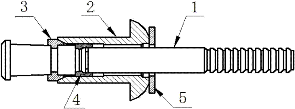
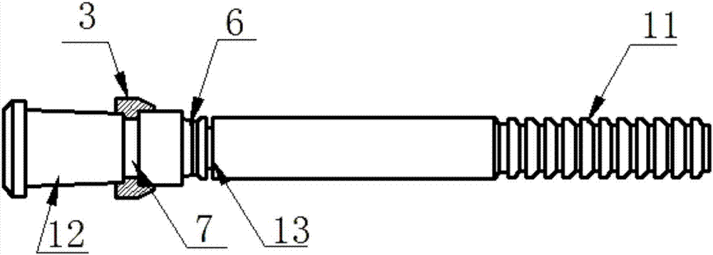
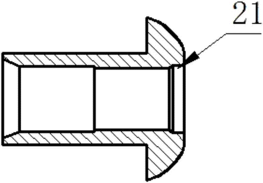

Image

  • Self-plugging rivet with high clamping force
  • Self-plugging rivet with high clamping force
  • Self-plugging rivet with high clamping force

Examples


Embodiment Construction

[0024] It should be noted that, in the case of no conflict, the embodiments of the present invention and the features in the embodiments can be combined with each other.

[0025] In describing the present invention, it should be understood that the terms "center", "longitudinal", "transverse", "upper", "lower", "front", "rear", "left", "right", " The orientations or positional relationships indicated by "vertical", "horizontal", "top", "bottom", "inner" and "outer" are based on the orientations or positional relationships shown in the drawings, and are only for the convenience of describing the present invention and Simplified descriptions, rather than indicating or implying that the device or element referred to must have a particular orientation, be constructed and operate in a particular orientation, and thus should not be construed as limiting the invention. In addition, the terms "first", "second", etc. are used for descriptive purposes only, and should not be understood ...


PUM


Abstract

The invention provides a self-plugging rivet with the high clamping force. The self-plugging rivet with the high clamping force comprises a core rod, a rivet sleeve and an expansion ring; the core rod comprises a clamping section and a riveting section; a neck breaking groove is formed between the clamping section and the riveting section; a groove is formed in the riveting section; the expansion ring is embedded into the groove; the rivet sleeve is locked on the core rod; the tail end of the rivet sleeve abuts against the expansion ring; and in the riveting and drawing processes, the riveting section is pulled into the rivet sleeve, the expansion ring is extruded out of the groove by the rivet sleeve, the tail of the rivet sleeve is expanded and deformed to form a projection, and the riveted core rod is broken at the position of the neck breaking groove. The self-plugging rivet with the high clamping force is suitable for occasions of single-surface fastening with higher inter-plate tensioning requirements and can be ensured to be consistent in the severe assembly application of large gap dislocation and slight hole dislocation, permanent fixed installation is realized, and gaps between plates can be eliminated; and meanwhile, a clamping ring of the self-plugging rivet is embedded in a clamping ring groove of the core rod so that the risk that the clamping ring falls off can be avoided, and the installation reliability can be improved.

Description

technical field [0001] The invention belongs to the field of fasteners, in particular to a self-locking blind rivet with high clamping force. Background technique [0002] Blind rivets are mainly used in parts where the structure is not open enough and needs to be operated on one side, such as the horizontal stabilizer of the aircraft, wings, engine nacelles, etc. The application of blind rivets can improve the internal structure design of the aircraft without reserving too much process space for installation. It can be used for metal material connection, and there are also special designs for composite material connection. [0003] Blind rivets for aerospace in the prior art are mostly composed of mandrel, nail sleeve, lock ring and other parts. During installation and use, the part below the broken neck groove of the mandrel is pulled into the nail sleeve to expand the nail sleeve and clamp it tightly. The interlayer fills the installation hole, can withstand large tensil...

Claims


Application Information

Patent Timeline
Patent Type & Authority Applications(China)
IPC IPC(8): F16B19/08
CPCF16B19/08
Inventor 贾晓娇郗建豪齐跃张晓斌张晓玲
Owner AEROSPACE PRECISION PROD INC LTD
Why Eureka
Try Eureka