Regular overlapped sub-array-based adaptive beamforming method

An adaptive beam and sub-array technology, applied in the field of radar, can solve the problems of increasing beam sidelobe, reducing output signal-to-interference-noise ratio, shrinking, etc., to achieve the effect of reducing beam sidelobe and improving output signal-to-interference-noise ratio

Active Publication Date: 2017-08-18
XIDIAN UNIV
View PDF5 Cites 2 Cited by
  • Summary
  • Abstract
  • Description
  • Claims
  • Application Information

AI Technical Summary

Problems solved by technology

Compared with regular non-overlapping sub-arrays, regular overlapping sub-arrays can effectively reduce grating lobes by reducing the phase center distance between sub-arrays. The sharing of the sub-arrays also has an impact, and the obvious problem is that the noise between the sub-arrays is no longer independent of each other, which can be regarded as beamforming in the background of colored noise
[0011] For beamforming in the background of colored noise, most of the existing methods use the estimation of the noise correlation matrix to pre-whiten the received data. Although this can perform better beamforming, it will increase the beam sidelobe and reduce the output signal interference. noise ratio

Method used


Image

  • Regular overlapped sub-array-based adaptive beamforming method
  • Regular overlapped sub-array-based adaptive beamforming method
  • Regular overlapped sub-array-based adaptive beamforming method

Examples


Embodiment Construction

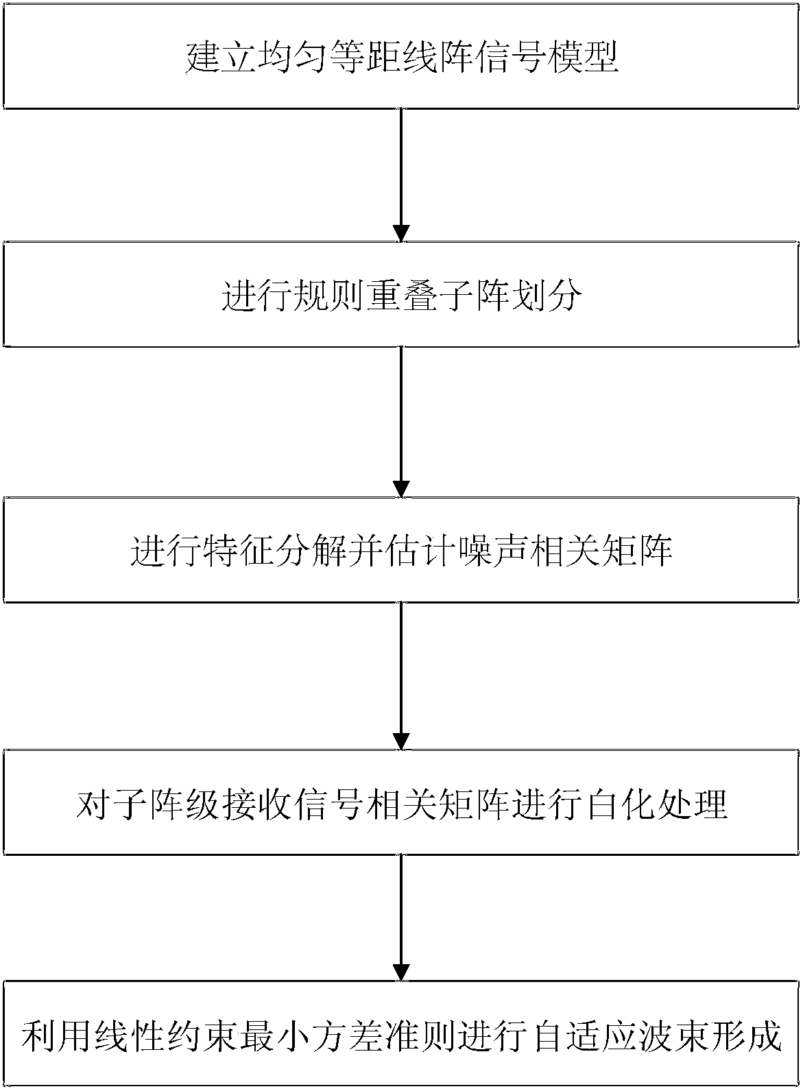
[0032] refer to figure 1 , the implementation steps of the present invention include as follows:

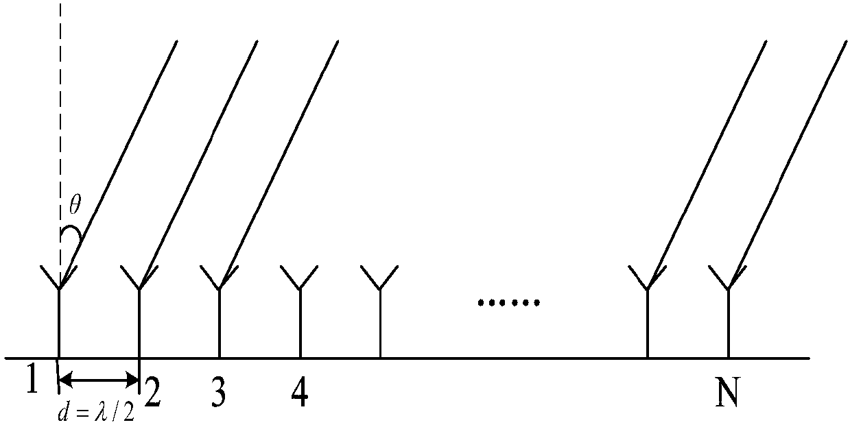
[0033] Step 1: Establish a received signal model X(t) at the element level of the uniform and equidistant linear array.

[0034] refer to figure 2 , the specific implementation of this step is as follows:

[0035] The receiving signal model is established by using an N-element uniform equidistant line array, the array element spacing d=λ / 2, and λ is the desired signal wavelength: 1a) Assume that the narrow-band far-field incident signal is s(t), and the incident direction is θ 0 , taking array element 1 as the reference point, the expected signal received by the array is expressed as:

[0036]

[0037] in, Indicates the signal received by the i-th array element, i∈{1,2,...i,...N}; Denotes the desired signal steering vector received by the array.

[0038] 1b) Assuming that the N×1-dimensional noise signal received by the selected uniform equidistant linear array is n(t...


PUM


Abstract

The invention discloses a regular overlapped sub-array-based adaptive beamforming method. The invention aims to solve the problems of high side lobe and low output signal to interference plus noise ratio in beamforming in the prior art. The realization process of the method includes the following steps that: 1) a uniform equidistant linear array element-level signal model is built; 2) regular overlapped sub-array division is performed on the equidistant linear array, a sub-array-level received signal model and a sub-array-level received signal correlation matrix are determined; 3) the sub-array-level received signal correlation matrix is transformed, eigenvalue decomposition is performed on the transformed sub-array-level received signal correlation matrix, small eigenvalues obtained through the eigenvalue decomposition are utilized to estimate noise power and a sub-array-level noise correlation matrix; 4) whitening processing is performed on the sub-array-level received signal correlation matrix according to the sub-array-level noise correlation matrix, so that a new correlation matrix can be formed; and 5) the new correlation matrix is utilized to perform adaptive beamforming based on a linearly constrained minimum variance criterion. With the method adopted, beam sidelobes are decreased, an output signal to interference plus noise ratio can be improved. The method can be used to process the influence of noises in a regular overlapped sub-array on beamforming.

Description

technical field [0001] The invention belongs to the technical field of radar, and specifically relates to an adaptive beam forming method, which can be used to deal with the influence of noise in regular overlapping subarrays on beam forming, so as to reduce beam side lobes and improve output signal-to-interference-noise ratio. Background technique [0002] The main research contents of array signal processing include adaptive beamforming and super-resolution direction of arrival estimation. Adaptive beamforming is also known as adaptive spatial filtering. Its essence is to enhance or suppress signals from different directions to obtain signals in the desired direction. It is widely used in radar, sonar, communication and other fields. [0003] Due to its wide application prospects, array signal processing algorithms have been developed rapidly in the past three decades, especially in the field of phased array radar, adaptive beamforming technology has been paid more and mor...

Claims


Application Information

Patent Timeline
Patent Type & Authority Applications(China)
IPC IPC(8): G01S7/36
CPCG01S7/36
Inventor 廖桂生郭学敏杨志伟王英刘永军王渊刘飞扬
Owner XIDIAN UNIV
Why Eureka
Try Eureka