
Tactile display device with touch needle self-locking function

A tactile display and self-locking technology, applied in the input/output process of data processing, input/output of user/computer interaction, instruments, etc. Problems such as high price, achieve high reliability, good stability, and reduce electromagnetic heating effects

Active Publication Date: 2017-08-18
ZHEJIANG SCI-TECH UNIV
View PDF13 Cites 8 Cited by
  • Summary
  • Abstract
  • Description
  • Claims
  • Application Information

AI Technical Summary

Problems solved by technology

[0005] Although many tactile assistive devices with similar functions have appeared on the market, the cost and price are too high, and the power consumption is also very large. Although the cost of other small-sized devices is controlled, they violate the common touch habits of blind people. and poor interactive experience
[0006] Therefore, the prior art lacks a tactile cognitive device for the blind that is low in cost, strong in experience, easy to carry and fast in response, can realize instant reading, can quickly refresh, and replaces visual pixels with contacts.

Method used


Image

  • Tactile display device with touch needle self-locking function
  • Tactile display device with touch needle self-locking function
  • Tactile display device with touch needle self-locking function

Examples


Embodiment Construction

[0025] The present invention will be further described below in conjunction with drawings and embodiments.

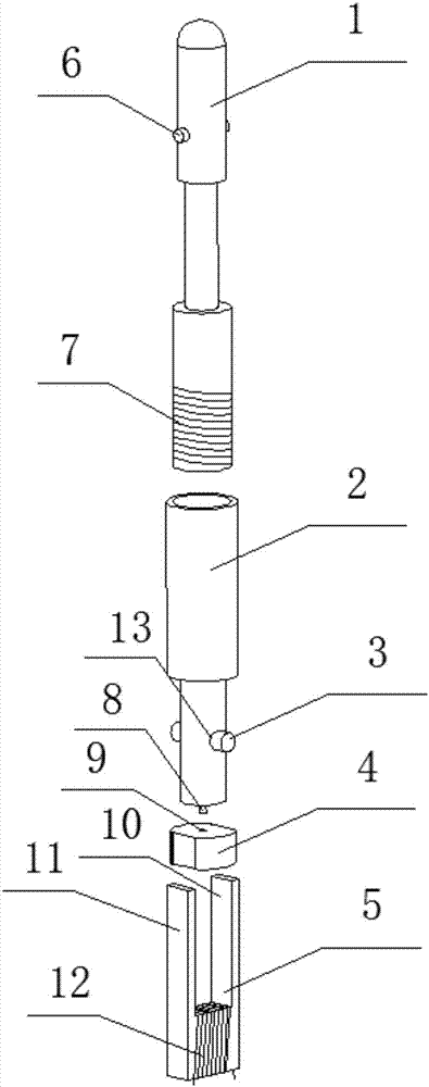
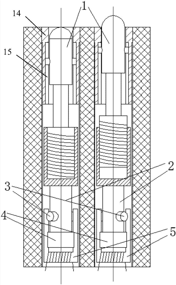
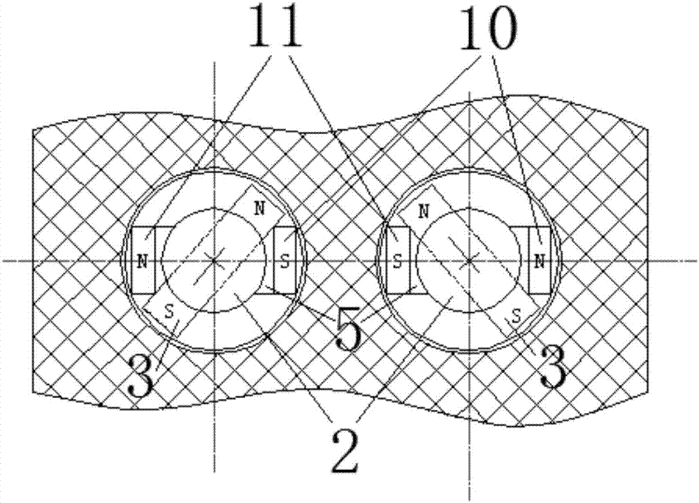
[0026] Such as figure 1 As shown, the specific implementation of the present invention includes a plurality of touch single needle components, and each touch single needle component is sequentially provided with a touch needle body 1, a rotating sleeve 2, a seat backing plate 4 and a U-shaped electromagnet 5 from top to bottom. .

[0027] Such as figure 1 As shown, the upper part of the touch needle body 1 is set in the top sleeve 14, and the symmetrical inner walls on both sides of the top sleeve 14 are provided with guide rail grooves 15 along the vertical axis, and the upper symmetrical outer walls of the touch needle body 1 are fixedly connected. There is a horizontal pin 6, and the horizontal pin 6 is embedded in the guide rail groove 15, so that the touch needle body 1 is limited to move up and down along the vertical axis; the lower part of the touch needle bod...


PUM


Abstract

The invention discloses a tactile display device with a touch needle self-locking function. According to the device, the upper portion of each touch needle body is installed in a top sleeve in a sleeved mode, each top sleeve is provided with guide rail grooves in the vertical axis direction, and a horizontal pin is fixedly connected to the upper portion of each touch needle body and embedded into the corresponding guide rail grooves; the lower portion of each touch needle body is installed in the upper portion of a rotary sleeve in a sleeved mode through a self-locking thread to form a lead screw rotating pair, each rotary sleeve is provided with a horizontal through hole, and a permanent magnet rod horizontally penetrates through each horizontal through hole; a short shaft is connected to each rotary sleeve, a center hole is formed in the center of the upper end of each bearing base plate, and each short shaft is inserted into the corresponding center hole to enable the corresponding rotary sleeve and the corresponding bearing base plate to form rotating pair connection; and each U-shaped electromagnet is mainly composed of a left electromagnetic pole wall, a right electromagnetic pole wall and a middle magnetic block, and each bearing base plate is placed between the left electromagnetic pole wall and the right electromagnetic pole wall of the corresponding U-shaped electromagnet and located on the corresponding middle magnetic block. The device is compact in structure, protrusion and self-locking of each touch needle body can be realized, and the device can be used for tactile display of Braille or graphs.

Description

technical field [0001] The invention relates to a linear motion electromagnetic drive device, in particular to a tactile display device with self-locking stylus. [0002] technical background [0003] At present, the number of blind people in the world has reached 285 million, and China is the country with the largest number of blind people in the world. Due to impaired vision, blind people can only obtain external information through touch and hearing, while traditional methods use paper to make tactile images or Braille characters for blind people to touch and recognize images or words. [0004] Compared with traditional paper materials, what the blind need more is a tactile display device that can refresh in real time and replace visual pixels with contacts, so as to quickly obtain image information. Through the real-time refreshing tactile display device, the blind can use the image or text in the tactile recognition device to understand the tactile image or text in a ve...

Claims


Application Information

Patent Timeline
Patent Type & Authority Applications(China)
IPC IPC(8): G06F3/01G06F3/046G09B21/00
CPCG06F3/01G06F3/046G09B21/003Y02D10/00
Inventor 杨文珍朱长健吴新丽汪文妃罗佳丽董露杰李昕严明
Owner ZHEJIANG SCI-TECH UNIV
Learn More