
Display screen, display device and mobile terminal

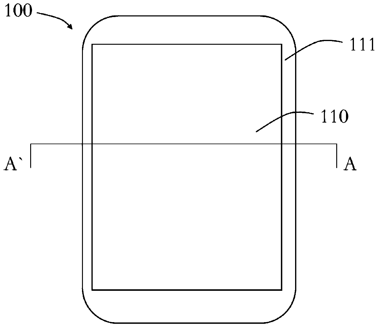
A technology for display screens and display parts, which is applied in the directions of identification devices, printing devices, projection devices, etc., and can solve problems such as poor camera lens installation, affecting shooting effects, and camera lens shaking, so as to improve the firmness of engagement and the stability of installation The effect of reducing the difficulty of processing

Active Publication Date: 2019-07-19
GUANGDONG OPPO MOBILE TELECOMM CORP LTD
View PDF5 Cites 0 Cited by
  • Summary
  • Abstract
  • Description
  • Claims
  • Application Information

AI Technical Summary

Problems solved by technology

During this installation process, it is required that the camera lens be installed in the display area with good firmness and high matching of assembly parts. If there is a gap between the display screen and the camera lens, it will cause the camera lens to shake in the display screen, so that the camera Poor lens installation affects the shooting effect

Method used


Image

  • Display screen, display device and mobile terminal
  • Display screen, display device and mobile terminal
  • Display screen, display device and mobile terminal

Examples


no. 1 example

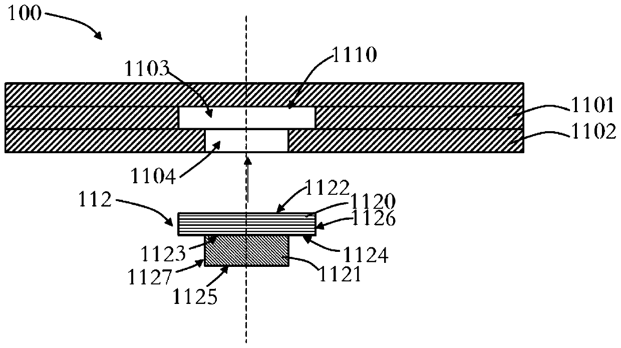
[0050] see Figure 5 As shown in FIG. 7 , the first groove 113 is disposed on the second bottom surface 1125 , and the first groove 113 is a square groove, and the first protrusion 114 is a square protrusion. Such a structural design can avoid rotational sliding between the first groove 113 and the first protrusion 114, and can further improve the alignment accuracy and installation of the camera lens 220 and the insert 112. Firmness.

no. 2 example

[0052] see Figure 8 , the first groove 113 is disposed on the second bottom surface 1125 , and the first groove 113 is provided with a concave arc surface 1131 . The first protrusion 114 has a convex arc surface 1141 matching the concave arc surface 1131 . With such a structural design, on the one hand, the concave arc surface 1131 is engaged with the convex arc surface 1141, so that the camera lens 220 is firmly installed under the display screen 100; The curved surface 1141 can be used as a concave light incident surface of the camera lens 220, and the concave light incident surface can converge light on the camera lens 220, that is, while the first protrusion 114 is used as an engaging part, It is also used as a lens element to optimize the shooting effect of the camera lens 220 .

no. 3 example

[0054] see Figure 9 , the first groove 113 is disposed on the second bottom surface 1125 , and the first groove 113 is provided with a convex arc surface 1132 . The first protrusion 114 has a concave arc surface 1142 matching the convex arc surface 1132 . With such a structural design, on the one hand, the concave arc surface 1142 is engaged with the convex arc surface 1132, so that the camera lens 220 is firmly installed under the display screen 100; The curved surface 1142 can be used as a convex light incident surface of the camera lens 220, and the convex light incident surface can diverge the light on the lens element of the camera lens 220, that is, the first protrusion 114 serves as an engaging At the same time, it also serves as a lens element to optimize the shooting effect of the camera lens 220.


PUM


Abstract

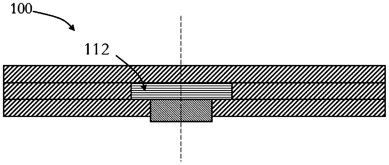
The invention provides a display screen. The display screen comprises a display portion, a non-display portion adjacent to the display portion, and an insertion piece. The display portion is provided with an insertion channel, and the insertion piece is fixed in the insertion channel. The insert piece comprises a light-permeable cover plate and a boss arranged on the light-permeable cover plate in a protruding mode, wherein the boss protrudes towards the side back on to a user relative to the light-permeable cover plate, and a clamping part matched with a camera lens is arranged on the boss. The invention also provides a display device. The display device comprises the display screen, and further comprises the camera lens and a middle frame. The display screen and the camera lens are fixed in the middle frame. The camera lens is arranged on the side, back on to the user, of the display screen and is clamped to the boss, so as to be positioned on the display portion. The invention further provides a mobile terminal. The installation stability of the camera lens and the display screen is improved.

Description

technical field [0001] The invention relates to the technical field of electronic equipment, in particular to a display screen, a display device and a mobile terminal with the display device. Background technique [0002] The display screen of an existing mobile terminal includes a display area for displaying images and a non-display area for installing a camera lens, etc. Such a structural design makes the screen ratio of the mobile terminal small and affects user experience. By installing the camera lens in the display area of ​​the display screen, the area of ​​the non-display area occupied by the camera lens can be effectively reduced, thereby increasing the screen-to-body ratio of the mobile terminal. During this installation process, it is required that the camera lens be installed in the display area with good firmness and high matching of assembly parts. If there is a gap between the display screen and the camera lens, it will cause the camera lens to shake in the di...

Claims


Application Information

Patent Timeline
Patent Type & Authority Patents(China)
IPC IPC(8): G09F9/00G03B29/00
CPCG03B29/00G09F9/00
Inventor 张海平
Owner GUANGDONG OPPO MOBILE TELECOMM CORP LTD
Learn More