Electric contact piece with built-in liquid cooling medium and spiral elastic contact element
An elastic contact and electrical contact technology, applied in the direction of contact parts, parts of connecting devices, electrical components, etc., can solve problems such as unusability, reduced reliability, and increased temperature rise, and achieve small insertion force, size and length. Demand reduction, high contact performance effect
- Summary
- Abstract
- Description
- Claims
- Application Information
AI Technical Summary
Problems solved by technology
Method used
Image
Examples
Embodiment 1
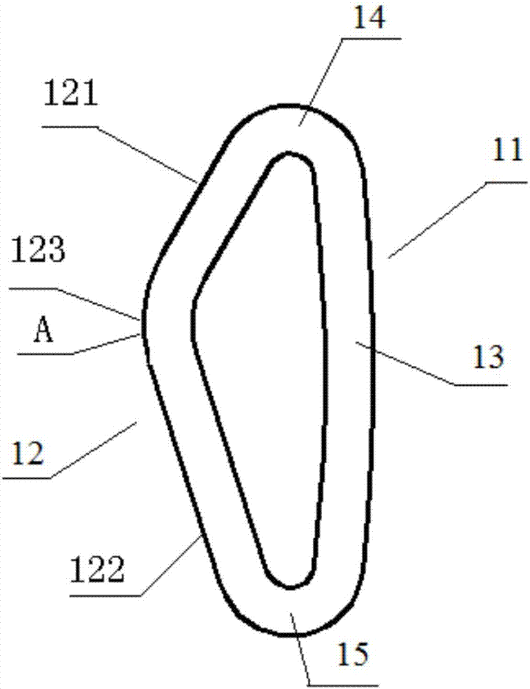
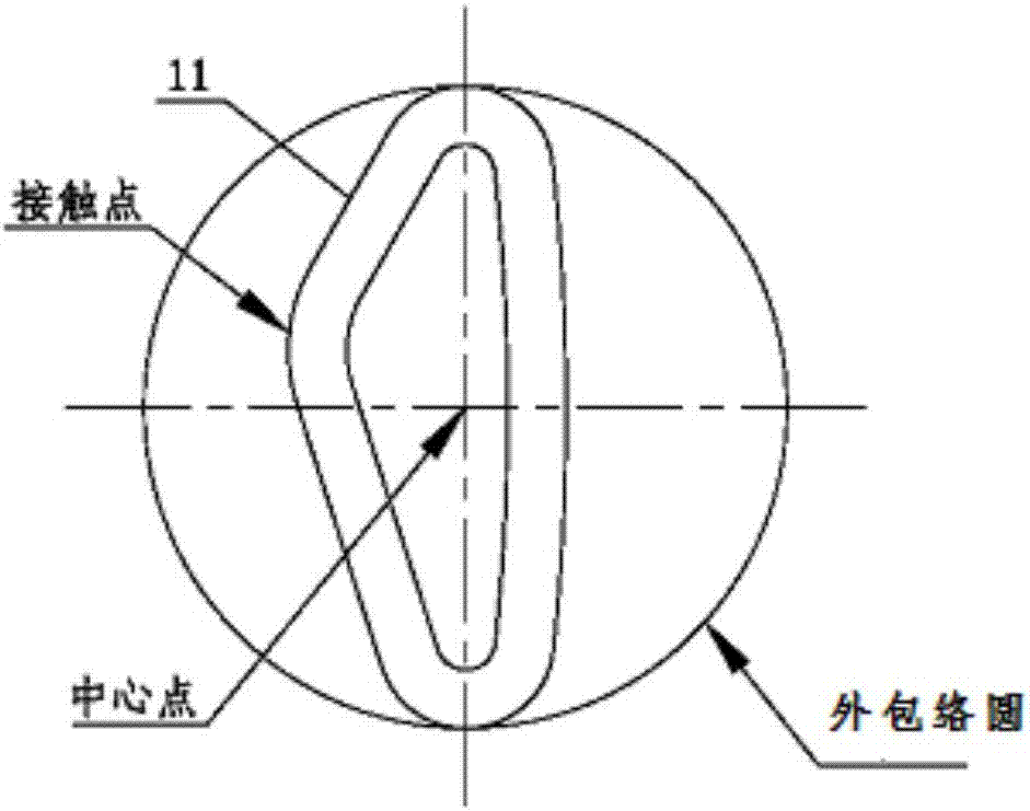
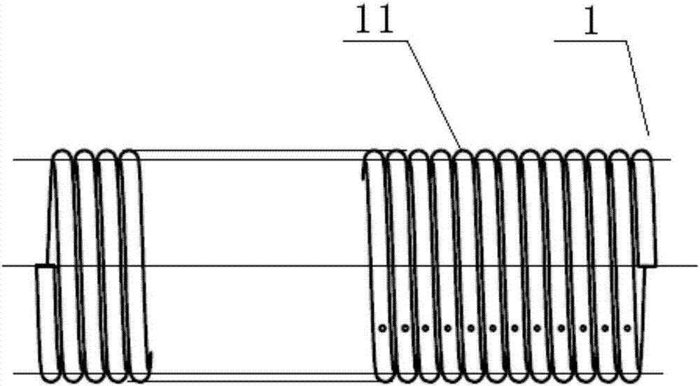
[0053] An electrical contact piece with an elastic contact element, comprising: an elastic contact element 1, the elastic contact element 1 includes a plurality of unit spiral rings 11, and the plurality of unit spiral rings 11 are sequentially connected end to end along a track line; the unit The spiral ring 11 is helically surrounded by a linear conductor. As shown in Fig. Two transition portions 15; the deformable contact portion 12 is arranged as a bent structure, including a guide area 121, a deformation area 122, a protrusion 123 connecting the guide area and the deformation area, and the length of the guide area 121 is less than the length of the deformation area 122 ( That is, the length of the line between the two end points of the guide zone is less than the length of the line between the two end points of the deformation zone), and the protrusion 123 is located on the line between the apex of the first transition portion 14 and the apex of the second transition porti...
Embodiment 2
[0086] In order to improve the stability of the electrical contact piece with elastic contact elements of the present invention and prevent the decrease in electrical conductivity due to deformation, in this embodiment, the difference from Embodiment 1 is that it also includes a support member 2, and the support member 2 It is located inside the elastic contact element 1.
[0087] Further, the outer wall of the support member 2 is partially or completely attached to the inner wall of the elastic contact element 1 to support the elastic contact element 1 .
[0088] In this embodiment, all the outer walls of the support member 2 can be fully attached to the inner wall of the elastic contact element (as shown in Figure 9(a)), at this time, the support member 2 is made of elastic material; or the support member 2 is in contact with the inner wall part of the fixed contact part 13 (as shown in Fig. 9(b) or Fig. 9(c)), which is used to limit the movement distance of the protrusion 1...
Embodiment 3
[0092] When the electrical contact works under high current or in the working state for a long time, a lot of heat will be generated, which will gradually increase the temperature inside the electrical contact. However, high temperature will have a great impact on the electrical conductivity of the electrical contact. Therefore, there is a need for an electrical contact with a built-in liquid cooling medium and an elastic contact element, which can continuously take away the internal heat of the electrical contact during the operation of the electrical contact, so as to ensure that the internal temperature of the electrical contact is constant. Good electrical conductivity of the electrical contact is thereby ensured.
[0093] The difference between this embodiment and embodiment 1 is:
[0094] The electrical contact with elastic contact elements with a built-in liquid cooling medium includes an elastic contact element 1 and a liquid cooling conduit 3 disposed inside the elast...
PUM
| Property | Measurement | Unit |
|---|---|---|
| Helix angle | aaaaa | aaaaa |
Abstract
Description
Claims
Application Information
 - R&D
- Intellectual Property
- Life Sciences
- Materials
- Tech Scout
- Unparalleled Data Quality
- Higher Quality Content
- 60% Fewer Hallucinations
Browse by: Latest US Patents, China's latest patents, Technical Efficacy Thesaurus, Application Domain, Technology Topic, Popular Technical Reports.
© 2025 PatSnap. All rights reserved.Legal|Privacy policy|Modern Slavery Act Transparency Statement|Sitemap|About US| Contact US: help@patsnap.com


