Connector Device Possessing Cable Connector And Installation Connector And Used Connector

A technology of connectors and cables, which is applied to parts of connection devices, two-part connection devices, connections, etc., which can solve problems such as cumbersome installation operations and difficulty in realizing robot automation

Active Publication Date: 2017-08-18
HIROSE ELECTRIC GROUP
View PDF6 Cites 12 Cited by
  • Summary
  • Abstract
  • Description
  • Claims
  • Application Information

AI Technical Summary

Problems solved by technology

[0006] In the above-mentioned conventional structure, in order to fit the first connector and the second connector, two actions, the movement action towards the vertical direction and the movement action towards the horizontal direction, are required, so the installation work is very cumbersome, for example, it is difficult to realize Automation using robots
[0007] In addition, since the connector is locked in the front-rear direction, especially at the rear (the side opposite to the side where the cable is installed), the size of the device is increased in the front-rear direction.

Method used


Image

  • Connector Device Possessing Cable Connector And Installation Connector And Used Connector
  • Connector Device Possessing Cable Connector And Installation Connector And Used Connector
  • Connector Device Possessing Cable Connector And Installation Connector And Used Connector

Examples


Embodiment Construction

[0046] A connector device according to a preferred embodiment of the present invention will be described with reference to the drawings. In addition, the electrical connector device is taken as an example for description here, of course, it is not intended to limit the present invention to the electrical connector device.

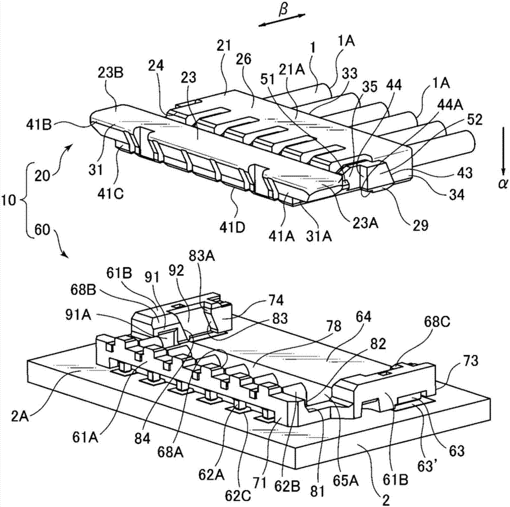
[0047] figure 1 is a top perspective view of the connector device 10 of the present invention, figure 2 is its top view. Although not explicitly shown in the drawings, the connector device 10 may have, for example, a longest width of about 10 mm and a height of about 1 to 3 mm. The connector device 10 includes a set of a connector 20 and a connector 60 . The connector 20 and the connector 60 are attached to the connector 60 mainly by bringing the connector 20 close to the connector 60 in the direction of the arrow "α" in the drawing while keeping their faces parallel ( As will be described later, "installation" in the present application includes, for ...


PUM


Abstract

A connector device provided by the present invention can simultaneously realize the motion towards a vertical direction and the motion towards a horizontal direction by one action. One end of a cable can be installed at one side of the peripheral surface of a first shell of a first connector, when the first connector is installed at a second connector, the inner circumferential surface of a second shell of the installable second connector is opposite to the outer circumferential surface of the first shell outside one side, and at least one part of the outer circumferential surface of the first shell opposite to the inner circumferential surface of the second shell is equipped with an inclined surface. The inclined surface is closer to the installation surface, and extends from one side of the cable to the other side along with the extension direction of the cable. The inclined surface impacts at least part of the second shell, so that during the process that the first connector is installed relative to the second connector, the first connector extends along the extension direction of the cable, relative to the second connector, and from one side of the cable to the other side.

Description

technical field [0001] The present invention relates to a connector device having a cable mountable connector and a mountable connector, and a connector used therefor. Background technique [0002] Patent Document 1 shows an example of such a connector device, particularly an electrical connector device. This connector device is composed of a set of a first connector and a second connector that can be fitted to each other. The first connector has a first housing and first terminals disposed on the first housing. The second connector includes: a second housing provided with a recess for the first housing; and a second terminal provided on the second housing and electrically connectable to the first terminal. [0003] The first housing is for use with a cable connector mounted at one end of the cable. The second housing can be used by being fixed to a mounting surface such as a mounting substrate. [0004] In this connector device, two operations are required for fitting t...

Claims


Application Information

Patent Timeline
Patent Type & Authority Applications(China)
IPC IPC(8): H01R24/00H01R13/46H01R13/627
CPCH01R13/46H01R13/6271H01R24/00H01R12/57H01R13/629H01R13/639
Inventor 吉沢俊彦
Owner HIROSE ELECTRIC GROUP
Why Eureka
Try Eureka