Humidity intelligent monitoring moisture-proof electric power device

A technology of intelligent monitoring and power equipment, applied in the field of switchgear, can solve the problems of incomplete dehumidification of the cabinet, incomplete dehumidification, etc., and achieve the effect of improving dehumidification efficiency, simple mechanism, and large humidity detection range

Inactive Publication Date: 2017-08-18
四川亚润科技有限公司
View PDF5 Cites 6 Cited by
  • Summary
  • Abstract
  • Description
  • Claims
  • Application Information

AI Technical Summary

Problems solved by technology

[0004] The technical problem to be solved by the present invention is that the dehumidification inside the cabinet is not complete, and the purpose is to p

Method used


Image

  • Humidity intelligent monitoring moisture-proof electric power device

Examples


Embodiment 1

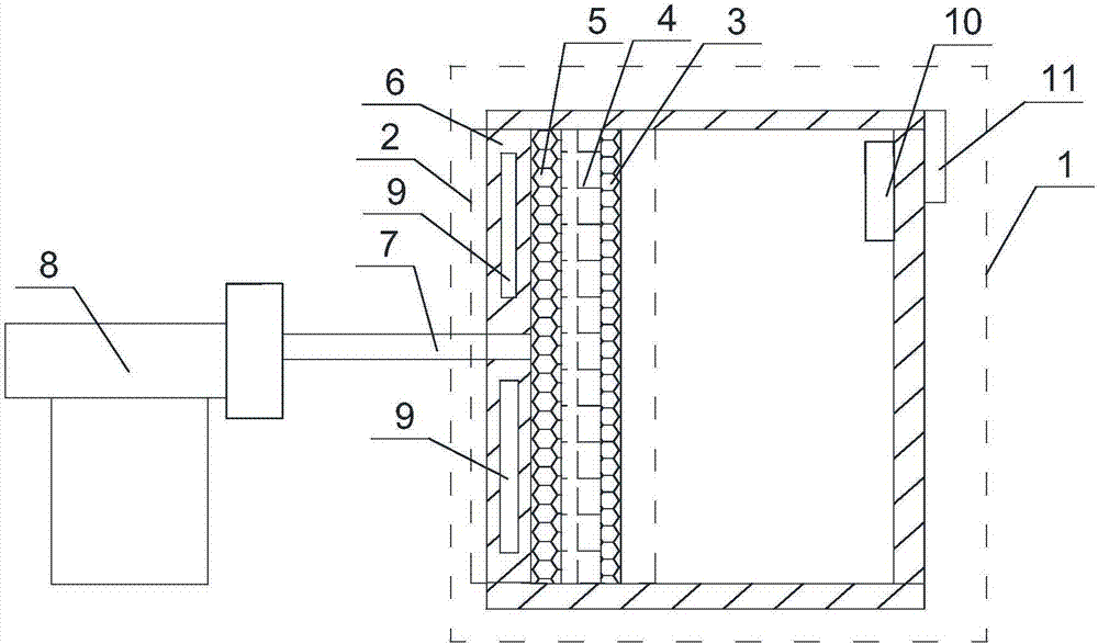
[0022] Such as figure 1 As shown, the moisture-proof power equipment for humidity intelligent monitoring of the present invention includes a cabinet body 1, one side of the cabinet body 1 is set as a jacket plate 2, and the jacket board 2 extends from the inside of the cabinet body 1 to the cabinet body 1 The direction of the outside includes the first hollow plate 3, the sponge plate 4 connected with the first hollow plate 3, the second hollow plate 5 connected with the sponge plate 4, the heat conduction plate 6 connected with the second hollow plate 5, and the heat conduction Inserted on the plate 6 is an air guide tube 7 communicating with the hollow hole of the second hollow plate 5 , the air guide tube 7 communicates with the vacuum pump 8 outside the cabinet body 1 , and at least two heating chips 9 are installed inside the heat conducting plate 6 . Both the first hollow plate 3 and the second hollow plate 5 are made of aluminum plates.

[0023] The realization method ...

Embodiment 2

[0025] Based on Embodiment 1, a humidity sensor 10 is installed inside the cabinet 1, the humidity sensor 10 is connected to a controller 11, the controller 11 is installed on the outer wall of the cabinet 1, and the controller 11 is connected to the vacuum pump 8 through an electronic switch. connect. The humidity sensor 10 is connected to a monitoring server through a wireless communication module, and the monitoring server is connected to a host computer. The humidity sensor, controller, and electronic switch are all existing structures, and the present invention only uses the humidity sensor, controller, and electronic switch to intelligently control the vacuum pump; after the humidity value detected by the humidity sensor is greater than the preset value, the controller controls An electronic switch turns on the vacuum pump. The humidity sensor will upload the humidity value to the host computer through the wireless communication module and the monitoring server, so as t...

Embodiment 3

[0027] Based on the above embodiment, an electric slide rail for the humidity sensor to slide up and down is installed on the other side of the cabinet body 1 opposite to the jacket plate 2, and the humidity sensor 10 is connected and fixed to the electric slide rail.

[0028] The humidity sensor automatically slides up and down along the electric slide rail, which increases the detection range of the humidity sensor, more comprehensive monitoring of humidity, and better humidity monitoring effect.


PUM


Abstract

The invention discloses moisture-proof power equipment for intelligent monitoring of humidity, which includes a cabinet body, one side of the cabinet body is set as a jacket plate, and the jacket board sequentially includes first The hollow plate, the sponge plate connected with the first hollow plate, the second hollow plate connected with the sponge plate, the heat conduction plate connected with the second hollow plate, the heat conduction plate is inserted with the hollow hole communicating with the second hollow plate An air guide tube, the air guide tube communicates with the vacuum pump outside the cabinet, and at least two heating sheets are installed inside the heat conducting plate. In the present invention, by modifying the mechanism of the side wall of the cabinet, the cabinet wall can dehumidify the interior of the cabinet in a concentrated manner, and the high water absorption of the sponge is used to firmly absorb the moisture on the sponge board to prevent the moisture from re-entering Inside the cabinet, the dehumidification efficiency is improved.

Description

technical field [0001] The invention relates to a switch cabinet, in particular to moisture-proof power equipment for intelligent monitoring of humidity. Background technique [0002] The main function of switchgear is to switch, control and protect electrical equipment during the process of power generation, transmission, distribution and power conversion in the power system. The components in the switch cabinet are mainly composed of circuit breakers, disconnectors, load switches, operating mechanisms, transformers and various protection devices. There are many classification methods of switch cabinets. For example, according to the installation method of circuit breakers, it can be divided into removable switch cabinets and fixed switch cabinets; or according to the different cabinet structures, it can be divided into open switch cabinets, metal-enclosed switch cabinets, and metal Closed armored switchgear; according to different voltage levels, it can be divided into hi...

Claims


Application Information

Patent Timeline
IPC IPC(8): H02B1/28G05D22/02
CPCH02B1/28G05D22/02
Inventor 何定旭
Owner 四川亚润科技有限公司
Why Eureka
Try Eureka