Sagging control method

A control method and technology for controlling parameters, applied in computational models, sustainable buildings, biological models, etc., can solve problems such as lack of memory, improve stability and reliability, and reduce parallel circulation.

A control method and technology for controlling parameters, applied in computational models, sustainable buildings, biological models, etc., can solve problems such as lack of memory, improve stability and reliability, and reduce parallel circulation.

CN107069831AActive Publication Date: 2017-08-18HUNAN UNIV

Image

  • Sagging control method
  • Sagging control method
  • Sagging control method

Examples


Embodiment Construction

[0023] The specific implementation manners of the present invention will be further described in detail below in conjunction with the accompanying drawings and embodiments. The following examples are used to illustrate the present invention, but are not intended to limit the scope of the present invention.

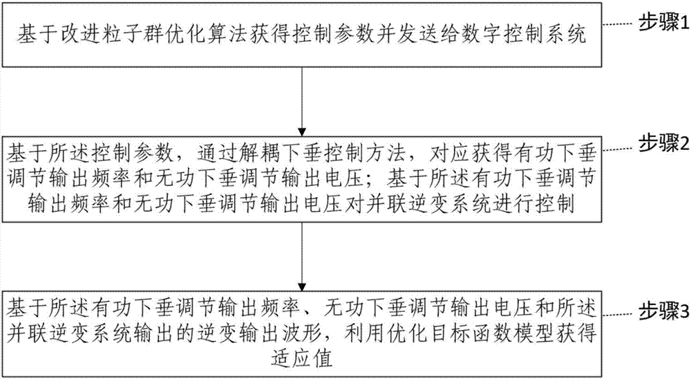
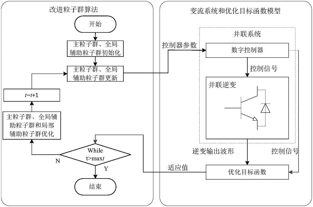
[0024] Such as figure 1 , in a specific embodiment of the present invention, shows a schematic flow chart of an overall droop control method. Generally, it includes: step 1, based on the initial fitness value, using the improved particle swarm optimization algorithm to obtain the control parameters;

[0025] Step 2, based on the control parameters, through the decoupling droop control method, correspondingly obtain the output frequency of active power droop regulation and the output voltage of reactive power droop regulation; system control;

[0026] Step 3, based on the active power droop regulated output frequency, the reactive power droop regulated output voltage and...


PUM


Abstract

The invention provides a sagging control method, and the method comprises the steps: proposing sagging control-decoupling sagging control; proposing an improved PSO (Particle Swarm Optimization) algorithm is proposed, which is an improved MMPSO with a multi-group and multi-speed updating mode; building an offline optimization model based on the improved PSO algorithm, wherein each inversion power supply in the model is in series connection with a reactor; supplying power to a load through parallel connection. The method can be used in the fields of new energy microgrids and uninterrupted power supply, can meet the parallel connection requirements of a plurality of inversion power supplies, can effectively reduce the parallel connection loop current, and improves the stability and reliability of a parallel connection system.

Description

technical field [0001] The present invention relates to the technical field of power electronic control, and more specifically, to a droop control method. Background technique [0002] Droop control means that according to the control target of the microgrid, the droop curve similar to that of the traditional generator is used to control the microsource, and the frequency active power droop characteristic (DroopCharacter) is used to dynamically distribute the unbalanced power of the system to each unit to ensure Unification of frequency and voltage in microgrid system. [0003] At present, the line impedances of parallel systems are different, and the coupling conditions of active power and reactive power are also different. Traditional droop control does not have power decoupling, so it is more dependent on the characteristics of line impedance. When the line impedance is inductive, the degree of power coupling is smaller than when the line impedance is resistive or resist...

Claims


Application Information

Patent Timeline
18 Aug 2017
Publication
CN107069831A
IPC
H02J3/46; G06N3/00
CPC
G06N3/006; H02J3/383; H02J3/46; H02J2203/20; Y02B10/10; Y02E10/56
Inventors
彭子舜; ēŽ‹äæŠ