Anchoring device for a spinal implant, spinal implant and implantation instrumentation

A technology for anchoring equipment and implants, applied in the direction of spinal implants, joint implants, joint implants, etc., can solve problems such as implant weakening, and achieve the effect of preventing movement

Inactive Publication Date: 2017-08-18
LDR MEDICAL SAS
View PDF8 Cites 1 Cited by
  • Summary
  • Abstract
  • Description
  • Claims
  • Application Information

AI Technical Summary

Problems solved by technology

For example, where the material of the implant is more flexible or less stable than the material of the anchor, there may be a risk of weakening the implant or retaining the anchor in the implant

Method used


Image

  • Anchoring device for a spinal implant, spinal implant and implantation instrumentation
  • Anchoring device for a spinal implant, spinal implant and implantation instrumentation
  • Anchoring device for a spinal implant, spinal implant and implantation instrumentation

Examples


Embodiment Construction

[0099] Various embodiments of the present disclosure will now be described with reference to the drawings of the present application, which, among other subjects, mainly relate to 3 groups of objects and their various combinations:

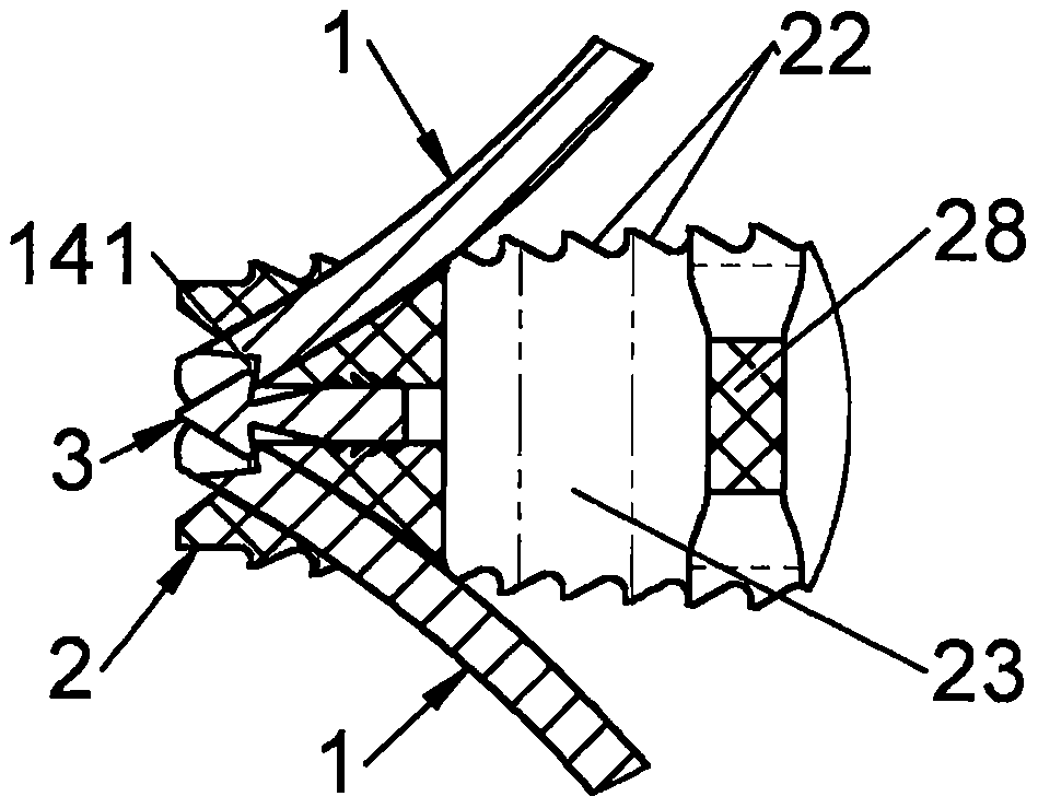
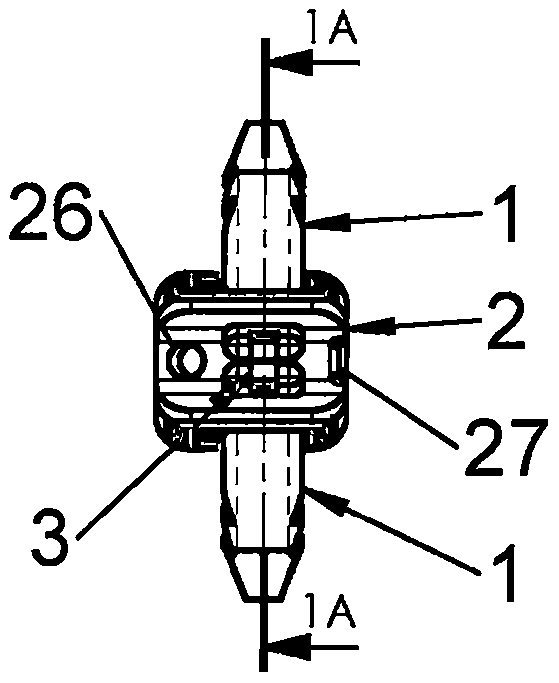
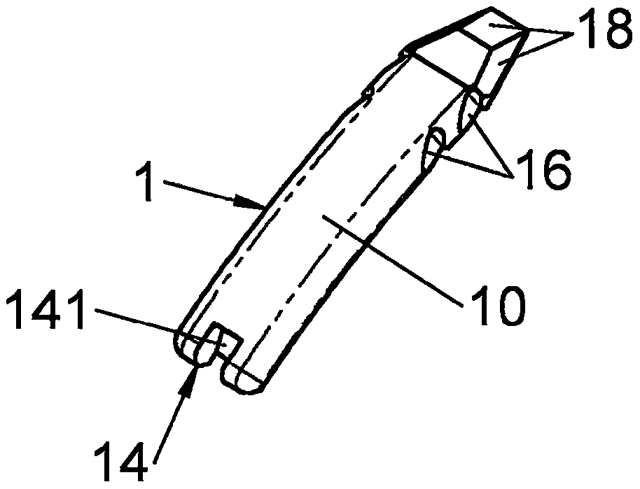
[0100] - an anchoring device (1) (or "attachment device" or further "anchor") and / or an anchoring system comprising several anchoring devices (1), which may be identical or different or even complementary to each other;

[0101] - an intervertebral implant (2) arranged to receive one or several of such devices (1) or anchoring systems, the intervertebral implant (2) including but not limited to being configured for Intermuscular fusion cages implanted via a posterior or transforaminal approach;

[0102] - Instruments (3, 4, 5) for implanting these implants (2) between the vertebrae and attaching them with such devices (1) or anchoring systems.

[0103] Each of these groups of objects may include various possible embodiments associated with a giv...


PUM


Abstract

The present invention relates to an anchoring device (1) for a rachidian implant (2), to an implant (2), to surgical instrumentation for the latter and to a rachidian surgery system, the anchoring device (1) comprising at least one stiff plate (10) with a longitudinal axis, configured so that its anterior end penetrates into at least one vertebral surface while its posterior end remains in a passage of the implant (2), characterized in that the implant (2) includes at least one means (3) for locking the device (1) relative to the implant (2) and in that the anchoring device (1) includes at least one abutment (14), said locking means (3) at least one flexible portion (30) and at least one abutment (31 ), cooperating with said abutment (14) of the device (1), the insertion of the anchoring device (1) into the passage allowing said abutment (31) of the locking means (3) to be pushed back by the flexibility of said flexible portion (30) which also allows mutual engagement of both abutments (14, 31) when they are found facing each other, by the elastic return of the flexible portion (30).

Description

technical field [0001] The present disclosure relates to orthopedic implants, including, for example, spinal (spine) implants such as intersomatic cages. An intermuscular fusion cage can be implanted between two adjacent vertebrae for placement and growth of a bone tissue graft (or substitute) in the disc space and for obtaining arthrodesis (fusion of two vertebrae) . For example, after placing the fusion cage in place, the intervertebral space is filled with autologous cancellous bone or a suitable bone substitute, which may also (or as an alternative) be placed in the fusion cage It is placed in the lumen of the fusion cage before being positioned in the gap. The present disclosure relates to intervertebral implants, such as intermuscular cages, but also to other types of implants, such as, for example, intervertebral disc prostheses or arthrodesis plates. Further, the present disclosure relates, among other subjects, to bone anchoring devices (anchors) for securing impla...

Claims


Application Information

Patent Timeline
Patent Type & Authority Applications(China)
IPC IPC(8): A61F2/44A61F2/46
CPCA61F2/4425A61F2/447A61F2/4611A61F2/4637A61F2002/30136A61F2002/30161A61F2002/30331A61F2002/30373A61F2002/30401A61F2002/30476A61F2002/30492A61F2002/305A61F2002/30517A61F2002/30579A61F2002/30604A61F2002/30772A61F2002/30782A61F2002/30841A61F2002/30879A61F2002/30889A61F2002/30904A61F2002/4641A61F2/4455A61B17/7064
Inventor H·查泰纳C·车布海P·伯纳德H·狄威利E·博格尔
Owner LDR MEDICAL SAS
Why Eureka
Try Eureka