
Improved nanocystalline ribbon preparation equipment

A nanocrystalline strip, an improved technology, applied in the direction of coiling strips, thin material handling, transportation and packaging, etc., can solve the problems of low surface utilization, tape reel falling, poor fit of driving slings, etc., to save The effect of using cost, reducing unloading time, and ensuring safety and reliability

Inactive Publication Date: 2017-08-22
LONDERFUL NEW MATERIAL NANTONG
View PDF7 Cites 2 Cited by
  • Summary
  • Abstract
  • Description
  • Claims
  • Application Information

AI Technical Summary

Problems solved by technology

[0002] In the manufacturing industry of amorphous and nanocrystalline strips, the positioning type strip winding technology is usually used for winding the strips. The positioning type strip winding equipment has the same problem, that is, The winding wheel on the winding equipment must be aligned vertically according to the exit position of the cooling roller. For example, when the exit position of the cooling roller is on the side, the take-up position of the winding wheel must also be on the corresponding side. However, when the take-up position is at the side, when unloading the entire strip after it has been wound, the driving sling is not well fitted because the strip is too far to the side, and it is easy to cause the accident of the tape falling, and the cooling The roller only uses three positions for spraying each time, and its surface utilization rate is low. Therefore, in order to solve the above problems, we have carried out corresponding technical improvements on the basis of the existing technology, and the original fixed positioning winding Become a variable rewinding position

Method used


Image

  • Improved nanocystalline ribbon preparation equipment

Examples


Embodiment Construction

[0014] In order to enable those skilled in the art to better understand the technical solutions in the present application, the technical solutions in the embodiments of the present application will be clearly and completely described below in conjunction with the drawings in the embodiments of the present application. Obviously, the described The embodiments are only some of the embodiments of the present application, but not all of them. Based on the embodiments in this application, all other embodiments obtained by persons of ordinary skill in the art without creative efforts shall fall within the protection scope of this application:

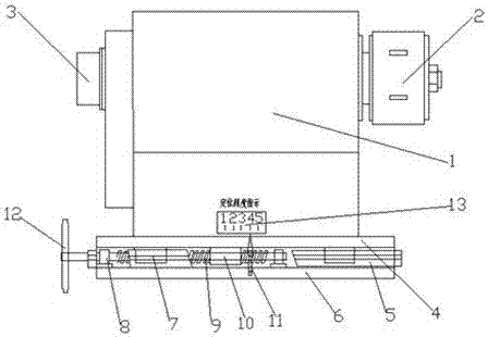
[0015] Such as figure 1 The shown improved nanocrystalline strip preparation equipment includes a winding device; the winding device includes a moving device and a cooling roll device installed on the moving device;

[0016] The moving device includes a cooling roll stand 6, a precision sliding guide rail 5 and a lead screw device; the cool...


PUM


Abstract

The invention discloses improved nanocrystalline ribbon preparation equipment which comprises a moving device and a cooling roller device mounted on the moving device. The moving device comprises a cooling roller base, a precision sliding guide rail and a lead screw device. The cooling roller base is horizontally arranged under the cooling roller device. The precision sliding guide rail is mounted on the cooling roller base. The lead screw device comprises a lead screw, lead screw bearing pedestals and a lead screw nut. The lead screw bearing pedestals are fixed to the two ends of the cooling roller base. The lead screw is horizontally fixed to the lead screw bearing pedestals. The cooling roller device comprises a cooling roller body and a winding wheel device mounted on the cooling roller body. According to the improved nanocrystalline ribbon preparation equipment, a fixed positioning winding station is changed into a variable winding station, the center of a winding wheel can be adjusted to the corresponding cooling roller ribbon discharging station no matter where the cooling roller ribbon discharging station is located, so that the problem of falling off of a ribbon reel during ribbon discharging hoisting is solved.

Description

technical field [0001] The invention relates to the field of production and manufacture of amorphous and nanocrystalline ribbons, in particular to an improved preparation equipment for nanocrystalline ribbons. Background technique [0002] In the manufacturing industry of amorphous and nanocrystalline strips, the positioning type strip winding technology is usually used for winding the strips. The positioning type strip winding equipment has the same problem, that is, The winding wheel on the winding equipment must be aligned vertically according to the exit position of the cooling roller. For example, when the exit position of the cooling roller is on the side, the take-up position of the winding wheel must also be on the corresponding side. However, when the take-up position is at the side, when unloading the entire strip after it has been wound, the driving sling is not well fitted because the strip is too far to the side, and it is easy to cause the accident of the tape ...

Claims


Application Information

Patent Timeline
Patent Type & Authority Applications(China)
IPC IPC(8): B65H18/04
CPCB65H18/04B65H2404/1361
Inventor 江沐风倪允康
Owner LONDERFUL NEW MATERIAL NANTONG
Learn More