Cylindrical sleeving joint framework of building

A cylindrical and architectural technology, which is applied in construction, on-site preparation of building components, building construction, etc., can solve problems such as limited application scope, inconvenient operation, deformation of pillars, etc., and achieve good economic and social benefits. , Improve stability and safety, and facilitate the effect of lifting height

Pending Publication Date: 2017-08-22
ANHUI AGRICULTURAL UNIVERSITY
View PDF6 Cites 3 Cited by
  • Summary
  • Abstract
  • Description
  • Claims
  • Application Information

AI Technical Summary

Problems solved by technology

[0002] With the development of the construction industry, the set frame is used to support the building or building being built or reconstructed, and it is also used for large mobile objects such as ships. It has the characteristics of simple assembly and disassembly, good load-bearing performance, safe and reliable use, etc. , the development speed is very fast, and it is also widely used in the advertising industry, municipal administration, traffic roads and bridges, mines and other departments, while the traditional single-pillar skeleton of the building can no longer meet the current requirements for rapid and safe construction
[0003] The traditional building skeleton often bears the pressure of four sides on one pillar, which easily leads to deformation of the footboard, handboard, upper and lower pillars, and its safety cannot be guaranteed. The traditional square skeleton is volatile. In practical applications, it is necessary to disassemble the screws. It is inconvenient to adjust the height of the footboard and the handboard, and the footboard and the handboard are on the same straight line, which can only realize the construction of a 90° corner. , Aiming at the above problems, a cylindrical nested skeleton of the building is proposed

Method used


Image

  • Cylindrical sleeving joint framework of building
  • Cylindrical sleeving joint framework of building
  • Cylindrical sleeving joint framework of building

Examples


Embodiment Construction

[0019] The following will clearly and completely describe the technical solutions in the embodiments of the present invention with reference to the accompanying drawings in the embodiments of the present invention. Obviously, the described embodiments are only some, not all, embodiments of the present invention. Based on the embodiments of the present invention, all other embodiments obtained by persons of ordinary skill in the art without making creative efforts belong to the protection scope of the present invention.

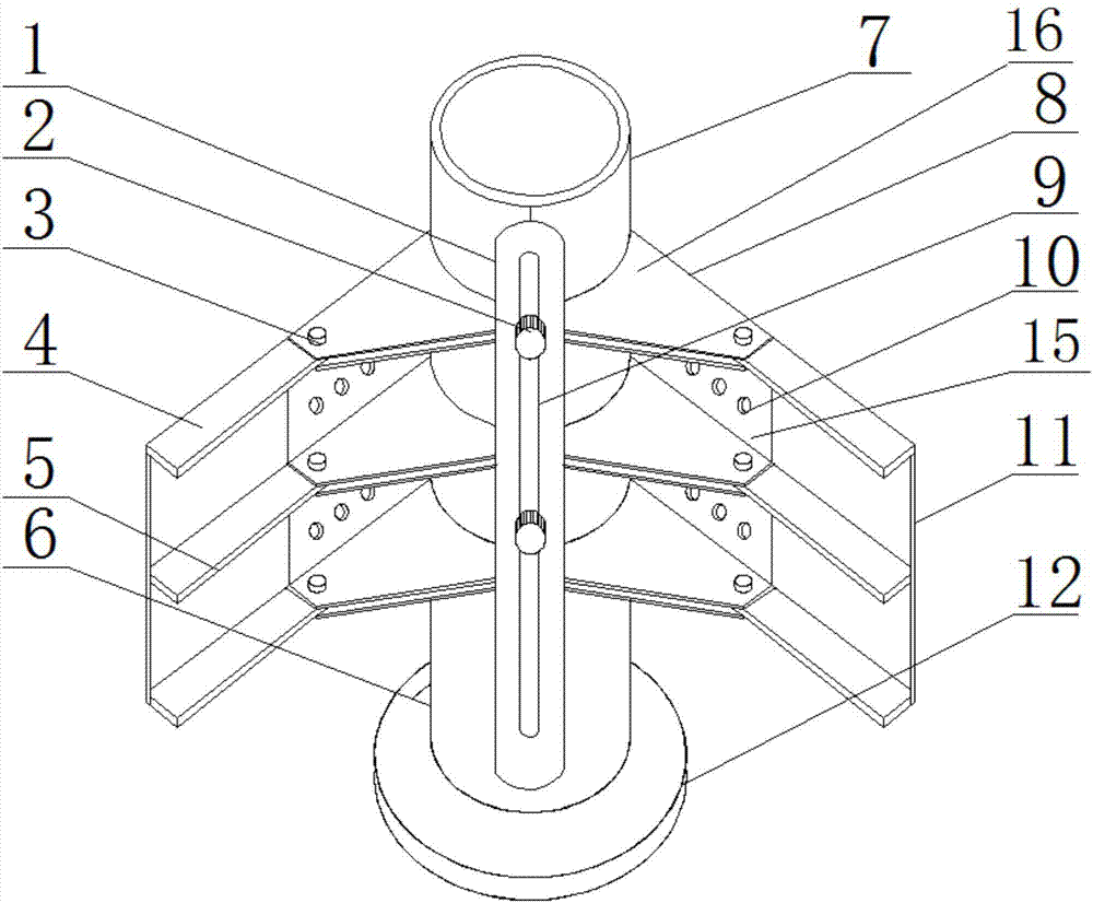
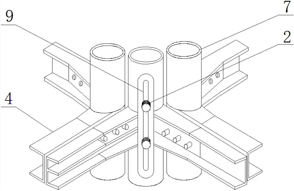
[0020] Referring to the accompanying drawings, the cylindrical sleeve frame of the building includes an upper pillar 7 and a lower pillar 6, the bottom of the lower pillar 6 is nested with a rubber base 12, and the two sides of the upper pillar 7 are respectively fixedly connected with a fixed strip 1, and the middle part of the fixed strip 1 There is a sliding groove 9, and there is a gap between the middle part of the fixing bar 1 and the upper pillar 7; the ...


PUM


Abstract

The invention discloses a cylindrical sleeving joint framework of a building. The cylindrical sleeving joint framework of the building comprises an upper support pillar and a lower support pillar. A rubber base is nested at the bottom end of the lower support pillar. Fixed strips are fixedly connected to the two sides of the upper support pillar. Sliding grooves are formed in the middles of the fixed strips, and the middles of the fixed strips are spaced from the upper support pillar. The upper support pillar is sleeved with foot plates. The cylindrical sleeving joint framework of the building is compact in structure and high in flexibility, the foot plates and hand plates are in sliding connection, the angle is adjusted freely, and the application range is extended; the single framework can be freely connected and cooperate with other frameworks, the phenomenon that a traditional framework bears surrounding pressure simultaneously through one support pillar is avoided, and stability and safety are greatly improved; the foot plates and the hand plates can slide flexibly in the sliding grooves, the lifting height can be adjusted freely, assembly and disassembly are simple, and the heights of the foot plates and the hand plates are changed freely; and the cylindrical sleeving joint framework of the building has good economic benefits and social benefits and is suitable for being used and promoted.

Description

technical field [0001] The invention relates to the technical field of construction machinery application, in particular to a cylindrical sleeve joint frame of a building body. Background technique [0002] With the development of the construction industry, the set frame is used to support the building or building being built or reconstructed, and it is also used for large mobile objects such as ships. It has the characteristics of simple assembly and disassembly, good load-bearing performance, safe and reliable use, etc. , The development speed is very fast, and it is also widely used in the advertising industry, municipal administration, transportation, roads and bridges, mines and other departments, while the traditional single-pillar skeleton of the building body can no longer meet the current requirements for rapid and safe construction. [0003] The traditional building skeleton often bears the pressure of four sides on one pillar, which easily leads to deformation of ...

Claims


Application Information

Patent Timeline
Patent Type & Authority Applications(China)
IPC IPC(8): E04B1/18E04G25/02
CPCE04B1/18E04G25/02
Inventor 刘素梅卫飞周海宝孙金鑫
Owner ANHUI AGRICULTURAL UNIVERSITY
Why Eureka
Try Eureka