Lamination apparatus

A technology of lamination device and lamination table, which is applied in the directions of separators/films/diaphragms/spacers, electrochemical generators, electrical components, etc., can solve the problems of inaccurate adjustment, time difference, and inability to perform rapid adjustment. , to achieve the effect of saving time and high accuracy

Pending Publication Date: 2017-08-22
东莞市冠逸自动化科技有限公司
View PDF3 Cites 2 Cited by
  • Summary
  • Abstract
  • Description
  • Claims
  • Application Information

AI Technical Summary

Problems solved by technology

[0007] First of all, it is difficult to achieve high-precision synchronization by starting the movement of the four pressing jaws entirely through the cylinder, and there is a time difference between the actions of each pressing jaw;
[0008] Secondly, the position of the pressure claw acting on the lamination platform is completely controlled by moving the cylinder, and the driving formation of the cylinder is determined, so for the same type of lamination, the pressure claw may fall on position A on the lamination platform. When changing the lamination model, or the pressure claw needs to fall on the B position of the lamination platform, then when the cylinder is formed to a certain extent, it cannot be adjusted quickly, and the position of the cylinder needs to be moved to adapt to the corresponding lamination model. It takes a long time to adjust the chip type, and the adjustment is not accurate enough, so it needs to go through many tests

Method used


Image

  • Lamination apparatus
  • Lamination apparatus
  • Lamination apparatus

Examples


Embodiment Construction

[0035] The present invention will be further described below in conjunction with specific embodiments and accompanying drawings.

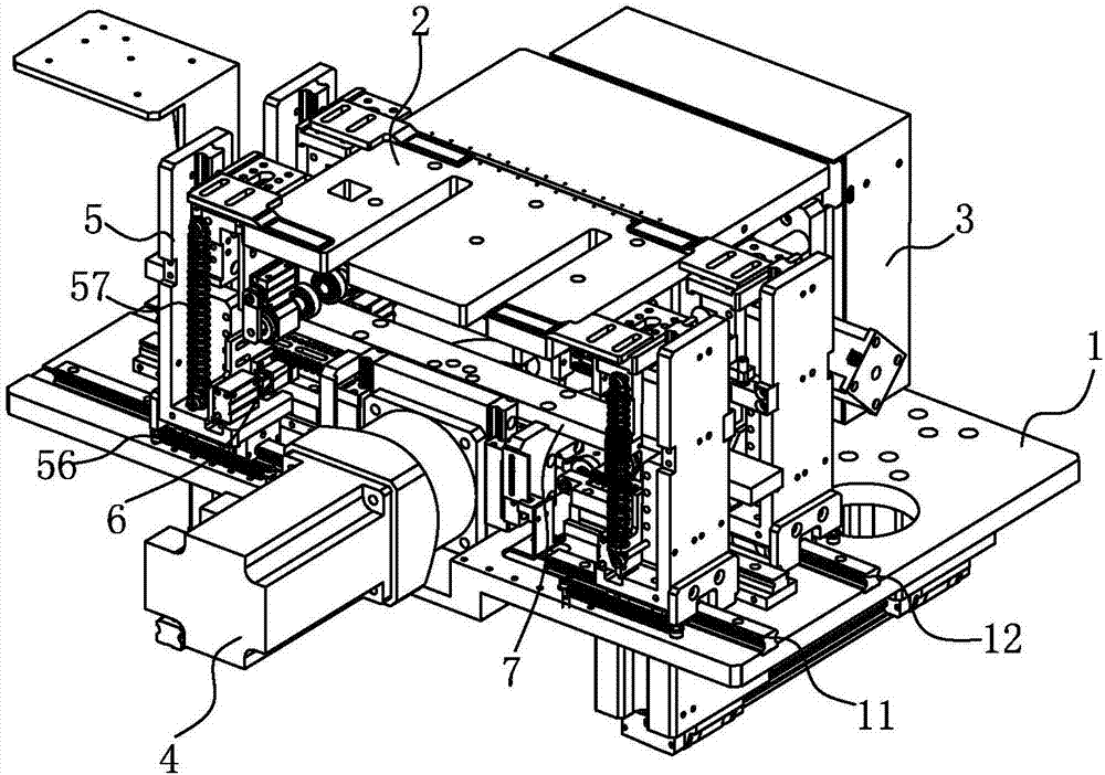
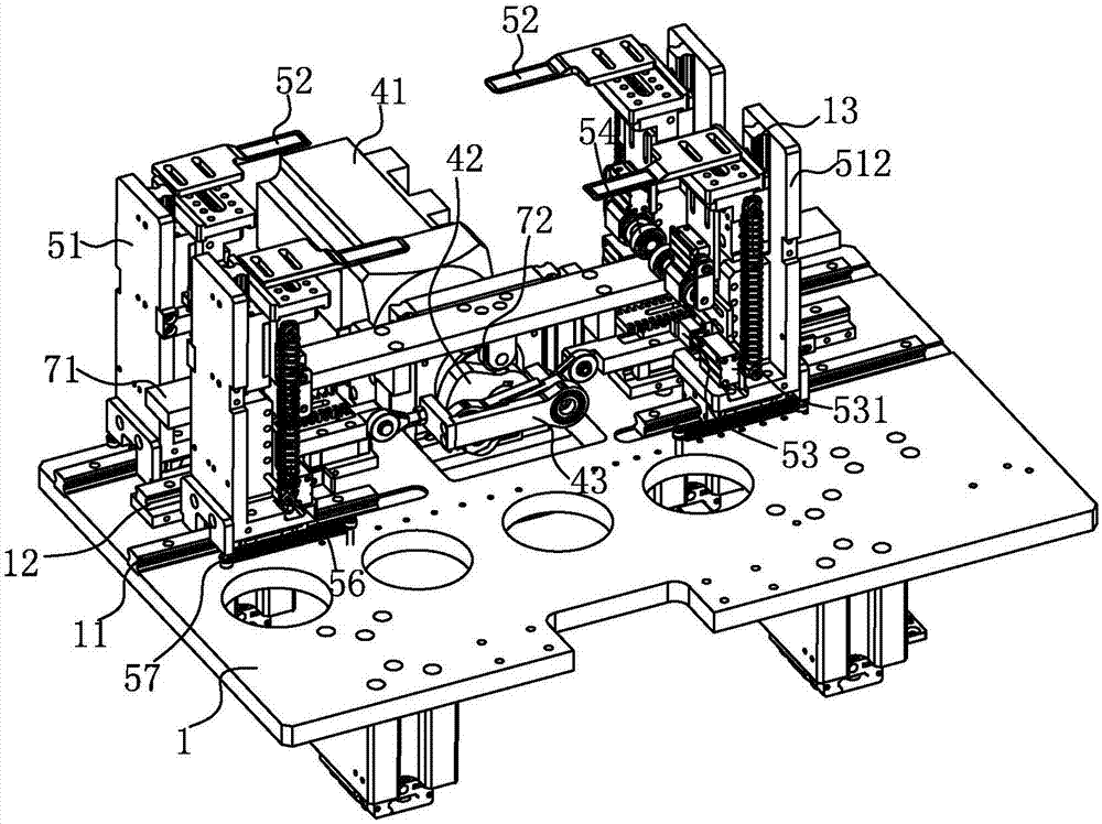
[0036] See figure 1 As shown, a lamination device has a large panel 1 for the installation of various components. The large panel 1 is installed on other equipment, and the lamination device can be combined with other equipment; Lamination platform 2, the lamination platform 2 is supported above the large panel 1 by a lamination lift drive mechanism 3, the lamination lift drive mechanism 3 can drive the lamination platform 2 to move up and down and left and right; the lamination platform 2 is located on the large panel The top of the panel 1 is parallel to the large panel 1 . On the large panel 1, a cam driving mechanism 4, a claw mechanism 5, a claw forward and backward switching mechanism 6 and a vertical lifting mechanism 7 are also installed.

[0037] Specifically, the cam driving mechanism 4 is arranged on the large panel and is located on t...


PUM


Abstract

The invention discloses a lamination apparatus, which has a large panel. A lamination platform is installed on the large panel. The lamination platform is supported above the large panel through a lamination lifting driving mechanism. The lamination platform is positioned above the large panel and is parallel to the large panel. A cam driving mechanism, a pressure claw mechanism, a pressure claw forwarding-withdrawing switching mechanism and a vertical lifting mechanism are also installed on the large panel. According to the invention, the cam driving mechanism replaces a traditional cylinder for driving, the vertical lifting mechanism is supported on the outer circumference of a curvy cam through a curve roller, the pressure claw advance and retreat switching mechanism is connected to the curvy cam through a transmission bar, the cam driving mechanism drives pressure claws to move up and down, and the curvy cam and the transmission bar drive the pressure claws to move side to side. Thus, synchronous action of the four pressure claws can be realized and the accuracy is high. During processing of laminations with different models, rapid regulation is carried out according to different models of the laminations and through different meshing position between a shift fork and a toothed bar. Thus, time is saved.

Description

[0001] Technical field: [0002] The invention relates to the technical field of battery processing equipment, in particular to a stacking device. [0003] Background technique: [0004] Lithium secondary batteries are widely used in daily life, and the secondary battery is composed of a battery assembly having a positive pole piece, a separator and a negative pole piece. The laminated assembly is to separate the positive and negative electrodes with a specified width and length with a separator, and stack them continuously according to the structure of positive electrode / diaphragm / negative electrode. [0005] The traditional stacking device includes: a stacking platform and four pressing claws acting on the four corners of the stacking platform, and the four pressing jaws are installed on a mounting bracket, the mounting bracket is installed on the large panel of the equipment, and the pressing jaws There is a horizontal driving mechanism and a vertical driving mechanism conn...

Claims


Application Information

Patent Timeline
IPC IPC(8): H01M10/0583H01M2/14H01M50/403
CPCH01M10/0583H01M50/40Y02E60/10Y02P70/50
Inventor 李华宁邓志乾王文龙胡健康
Owner 东莞市冠逸自动化科技有限公司
Why Eureka
Try Eureka